
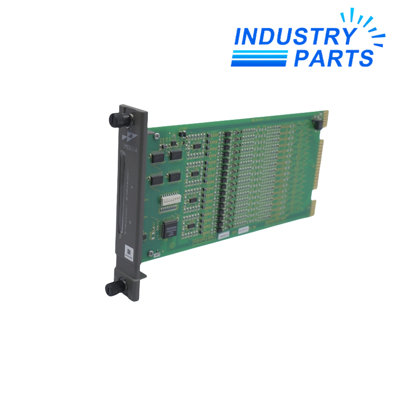


ABB Bailey IMDSI14 48 VDC Digital Input Module
A fixed-range 48 VDC digital input module that transfers sixteen field states to the Bailey control system.
Overview
IMDSI14 is an ABB Bailey Harmony digital input module for sixteen 48 VDC process signals. Contact closures, switches and powered status circuits are conditioned, isolated and presented to the controller through the rack I/O expander bus.
The 48 VDC input class is fixed and requires no input-voltage jumper selection. Do not confuse IMDSI14 with the 24 VDC IMDSI13 or the multi-voltage IMDSI22.
Specs
| Manufacturer | ABB Bailey |
|---|---|
| Model | IMDSI14 |
| Product Family | Harmony rack I/O / INFI 90 |
| Product Type | Digital input module |
| Input Channels | 16 digital inputs |
| Field Input Class | 48 VDC |
| Configuration | Fixed 48 VDC; no voltage-selection jumpers |
| Input Response | 17 ms fixed debounce for DC inputs |
| Isolation | 1,500 VDC between input and logic circuitry and between input channels |
| Input Conditioning | Current limiting and optocoupler isolation |
| Channel Indication | Front-panel LEDs arranged for the input groups |
| System Interface | I/O expander bus |
| Addressing | Module address selected before installation |
| Field Connection | Termination unit and I/O cable matched to the rack design |
| Control-System Role | Interfaces discrete process status signals to the controller |
| Important Distinction | IMDSI13 is 24 VDC; IMDSI22 supports selectable input voltages |
Features
- Provides sixteen discrete status points for process monitoring and control logic.
- Uses optocouplers to separate field circuits from module logic.
- Includes fixed debounce appropriate for typical DC contact inputs.
- Retains a fixed 48 VDC design to avoid ambiguous voltage jumper settings.
Applications
- Pump, valve and breaker status monitoring in 48 VDC control systems.
- Alarm and permissive inputs in legacy Bailey INFI 90 or Symphony installations.
- Exact replacement of an existing 48 VDC digital input position.
Lifecycle
- Record module address, slot, termination code and every channel assignment.
- Confirm actual field voltage and common wiring before connecting a replacement.
- Use static-safe handling and keep field power isolated during installation.
- Test each input indication and the corresponding controller reference before returning the process to automatic control.
FAQ
Can IMDSI14 be used in place of a 24 VDC IMDSI13?
No blanket substitution should be made. IMDSI14 is fixed for 48 VDC inputs, so the field-voltage design and termination must match.
Which records should accompany an IMDSI14 quotation?
Provide the module label, rack and slot, address setting, termination-unit code, field voltage and a sixteen-point I/O schedule.
What should be checked if an IMDSI14 channel remains off after replacement?
Verify field power, common wiring, contact state, termination cable, controller mapping and module address before attributing the symptom to hardware.
How can an IMDSI14 exchange be commissioned without creating false trips?
Force or inhibit affected logic only under an approved procedure, then test each point from the field device through to the operator display.
Why does the debounce behavior of IMDSI14 matter to a retrofit?
A replacement path must preserve expected response to contact bounce and short pulses; applications requiring faster event capture need a separate functional review.
Recommended Models
| 025-39956-000 | Nord SK 90SH/4 | BNS 519-D04-D12-100-10-FD |
| E3 1051.1/A004-3 | AC2671 | Honeywell 998MX |
| SR3B261BD SR3 XT141BD | SD4n | PLC-RPT-60DC/21-21 |
| SK3105.190 | PC400/600 | 201-A |
| ST91B | 972LX IS23DI0XCD000 | 6DS1606-8BA |
| KFH-R/A/0/X/1370 | 3G3MX2-A2037-E | DALIKNX2CH |
| 0285-0135 | ION7300-TROP | BB-2000L |
| STR8102D | 6SY70000AA83 | DNC-125-320-PPV-A-KP |
| XTP OUTPUT LOAD BD | MHFP014BSSW | B30C-1125-855-WT Y3800686 |
| FP208-277-70501 | KST-87-12MPM8-ZB1 | 700479702 |