

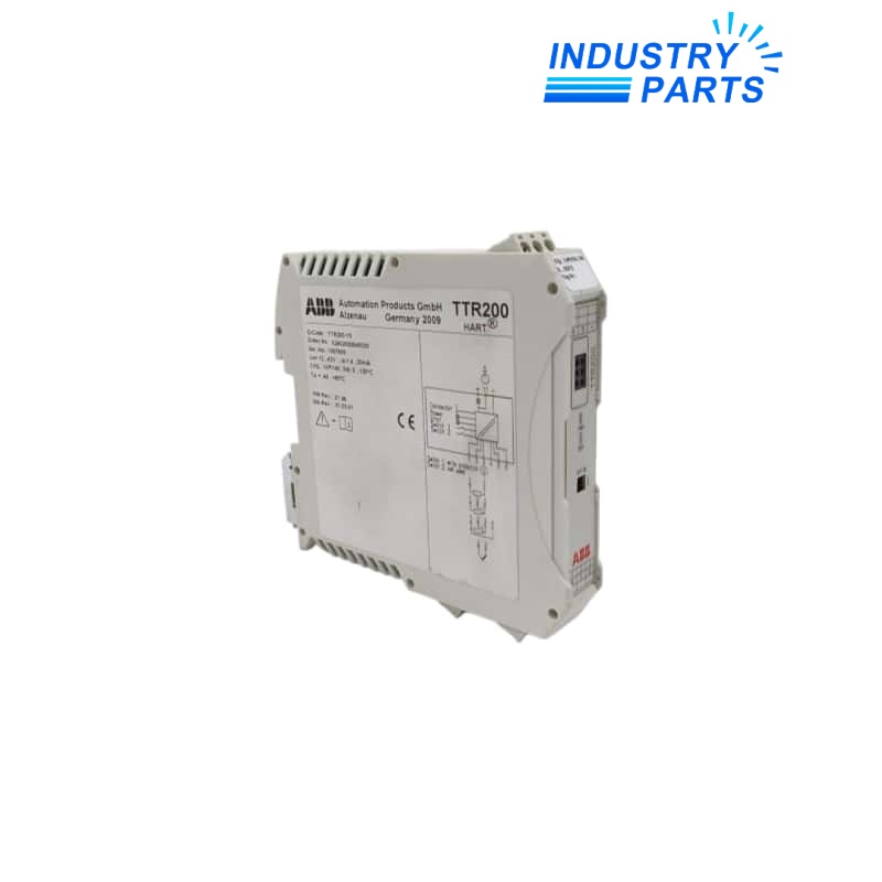
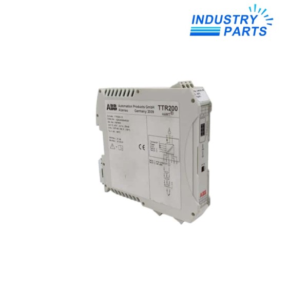
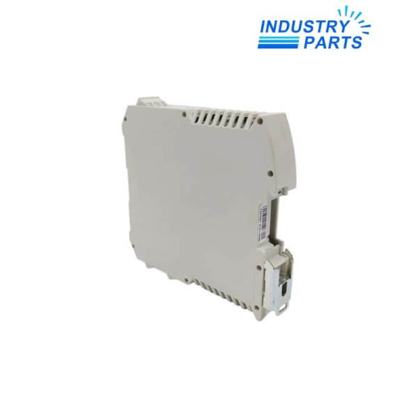
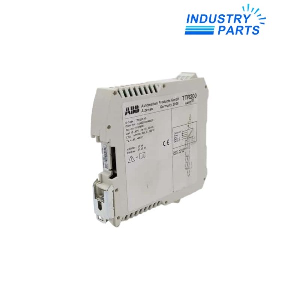
ABB TTR200 Rail-Mount HART Temperature Transmitter
01Technical Summary
ABB TTR200 is a universal rail-mount temperature transmitter in a compact 17.5 mm housing. It accepts RTD, thermocouple, resistance, and millivolt inputs and converts the configured measurement to a 4...20 mA signal with HART communication, diagnostics, local write protection, and hazardous-area approval options.
02Specifications
| Manufacturer | ABB |
|---|---|
| Model | TTR200 |
| Product Type | Rail-mount temperature transmitter |
| Sensor Inputs | RTD, thermocouple, resistance, and millivolt |
| Output | Configurable 4...20 mA or 20...4 mA with HART |
| Supply Voltage | 11...42 V DC, non-Ex; 11...30 V DC, Ex applications |
| Accuracy | 0.1% |
| Long-Term Stability | 0.05% per year |
| Measured-Value Update | 10 updates per second |
| Electrical Isolation | 3.5 kV DC for 60 s, input to output |
| Ambient Temperature | -40...+85 deg C |
| Humidity | 5...95% RH climate class; up to 100% RH per specified test |
| Enclosure Rating | IP20 or rating of installation housing |
| Mounting | 35 mm rail |
| Functional Safety | SIL 2 / SIL 3 capability per IEC 61508 |
| Diagnostics | NE89 wire-break / corrosion monitoring and NE107 status |
| Hazardous-Area Options | ATEX, IECEx Zone 0, FM / CSA |
03Features
Design and Function
- Universal sensor input reduces the number of transmitter types required for common temperature applications.
- Green PWR and red ERR LEDs provide immediate cabinet-level status.
- Hardware write protection can be enabled by DIP switch.
- One-point and two-point sensor error adjustment are supported.
- HART communication enables remote configuration and diagnostic access.
- Configurable overrange and underrange current behavior supports control-system fault handling.
- The compact rail housing is suited to densely populated control cabinets.
Verified Identity
Manufacturer: ABB
Model: TTR200
Product Type: Rail-Mount HART Temperature Transmitter
04Compatibility
- Select the exact sensor type, connection method, measuring range, units, and failure-current behavior before commissioning.
- Use a HART-compatible supply isolator or DCS input path; where required, maintain the documented HART loop resistance.
- Verify whether the ordered transmitter carries the hazardous-area and functional-safety approvals required by the project.
- Install the unit on a 35 mm rail in a housing that provides the required environmental protection.
- TTR200 is related to the TTH200 platform but is the rail-mount version with its own housing and terminal arrangement.
05Replacement & Lifecycle
- Export or record the configured sensor, range, damping, failure current, trim data, tag, and write-protection setting.
- Check polarity, loop voltage, load resistance, grounding, and sensor wiring before energizing the replacement.
- After installation, verify at least two measurement points and confirm HART communication and diagnostic status.
- For SIL service, follow the applicable ABB safety manual and proof-test requirements.
- Do not substitute a head-mount transmitter without reviewing mounting, terminals, loop design, approvals, and configuration access.
06Applications
- RTD and thermocouple measurement in process control cabinets.
- Millivolt and resistance conversion to 4...20 mA.
- HART-enabled temperature loops requiring cabinet-mounted signal conditioning.
- Hazardous-area sensor circuits using an appropriately ordered and certified TTR200 version.
FAQFrequently Asked Questions
Which sensors can TTR200 accept?
It accepts RTDs, thermocouples, resistance inputs, and millivolt sources.
What output does it provide?
The output is configurable as 4...20 mA or reverse 20...4 mA with HART communication.
How is local status indicated?
A green LED indicates power and a red LED indicates a sensor, lead, or transmitter fault.
Can the configuration be protected?
Yes. A DIP switch provides local hardware write protection.
Is TTR200 suitable for safety applications?
ABB documents SIL 2 and redundant SIL 3 capability when the applicable IEC 61508 requirements are followed.
What should be verified after replacement?
Verify sensor wiring, loop voltage, configured range, failure behavior, HART communication, diagnostics, and measurement accuracy.
+Recommended Models
| RTX40 | ABB GHQ6050061R001 | TS16 T3 |
| UE4740-22H0000 | KCD2-SR-EX1.LB | G3439 6470 800 |
| M71C-2000-595-TN | SB-910 | PCO1AD0CS0 |
| ABB Sv / S 30.640 | 5104A | MA1500 |
| 5975-1001-9082 | EY-IO550F001 | GMS-ODC 84130104 |
| XPSAV11113 | IR4014 | 820BA231 |
| 01151-0011-0032 | DSU110F001 | Extech 407910 |
| 60947-5-6 | GP2301H-LG41-24V 3080028-03 | YC-1SDA038301R1 |
| 5WG1510-1AB03 | KFD2-STC4-EX1-KFD2-STC4-EX1-KFD2 | ABB M251022CR 800-0-8049 |
| KMD-1161W | EL3164 | IO88B01KNX |


