


Dynamix 1444 | Dynamic measurement module
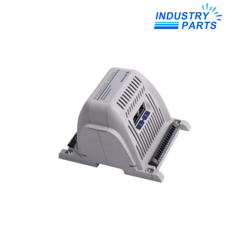
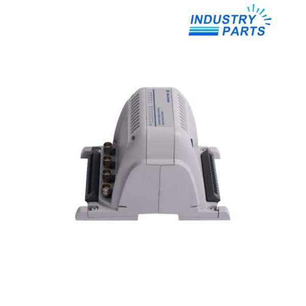
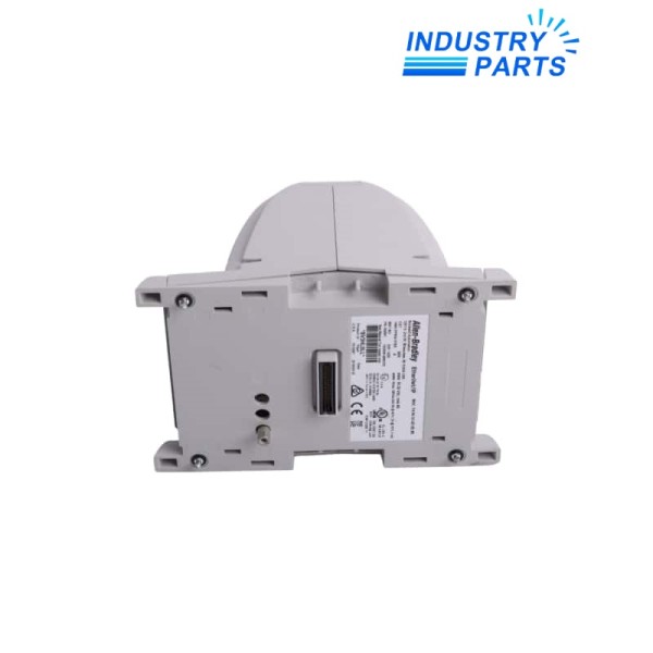
Allen-Bradley 1444-DYN04-01RA Dynamix Measurement Module
A four-channel dynamic measurement main module with two speed inputs, four buffered outputs, EtherNet/IP connectivity and expandable relay capability.
BrandAllen-Bradley
Model1444-DYN04-01RA
Identification1444-DYN04-01RA
01 /
Key Information
1444-DYN04-01RA is the main measurement module in the Allen-Bradley Dynamix 1444 condition-monitoring platform. Four dynamic input channels accept IEPE accelerometers, eddy-current probe signals or voltage inputs, while two dedicated speed inputs support machine-reference measurements.
The module combines measurement processing, buffered signal access and EtherNet/IP communication. One onboard SPDT control relay is provided, and relay expansion modules can extend the local alarm-output arrangement when required by the monitoring strategy.
02 /
Functions
- Acquires four dynamic measurement channels for vibration and related machine-condition signals.
- Supplies compatible IEPE transducers and supports eddy-current probe and voltage signal configurations.
- Accepts two speed-reference inputs for order, phase and rotational measurement functions.
- Provides four buffered outputs for access to the conditioned channel signals.
- Communicates measurement, status and configuration data over EtherNet/IP.
- Operates one onboard SPDT relay and supports as many as three four-relay expansion modules.
03 /
Specifications
| Manufacturer | Rockwell Automation |
|---|---|
| Brand | Allen-Bradley |
| Product Family | Dynamix 1444 |
| Catalog Number | 1444-DYN04-01RA |
| Dynamic Input Channels | 4 |
| Speed Inputs | 2 |
| Buffered Outputs | 4 |
| Supported Input Context | IEPE accelerometers, eddy-current probes and voltage signals |
| Onboard Relay | 1 SPDT control relay |
| Relay Expansion | Up to 3 optional 1444-RELX00-04RB modules |
| Ethernet Connections | 2 |
| Network | EtherNet/IP |
| Supply Inputs | Two redundant 18 to 32 V DC inputs |
| Current Consumption | 411 mA at 24 V DC |
| Power Consumption | 11.5 W |
| Power Dissipation | 9 W |
| Status Indicators | 16 |
04 /
Installation
- Mount the main module and any expansion modules on properly grounded DIN rail in the documented enclosure environment.
- Connect SELV 18 to 32 V DC power and preserve the redundant-supply arrangement where the installation uses both inputs.
- Configure each dynamic channel for its actual transducer type, sensitivity, bias behavior and engineering units.
- Keep buffered-output and sensor cables routed for low-noise condition-monitoring signals.
- Record the EtherNet/IP address, controller connection, alarm setpoints, relay logic and tachometer configuration before exchange.
- Validate channel bias, speed reference, measurement values and relay actions after commissioning.
05 /
Lifecycle
- Maintain the complete 1444-DYN04-01RA catalog number because the main measurement module and its expansion units have different roles.
- Archive the Dynamix configuration and controller integration before replacing an installed module.
- Preserve the physical channel-to-transducer map; similar sensors can require different power and scaling settings.
- Match optional relay expansion quantity and local-bus order to the existing alarm design.
- Confirm supported module firmware and Add-On Profile versions in the Rockwell engineering environment before service.
