

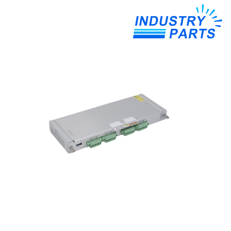

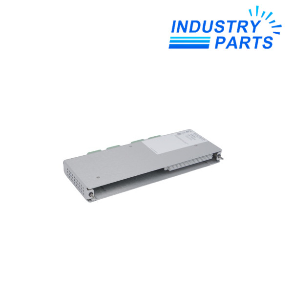

Bently Nevada 125720-01 Spare 4-Channel Relay Output Module
The standard rear relay-output module for a Bently Nevada 3500/32M four-channel relay assembly.
Product Profile
Bently Nevada 125720-01 is the spare four-channel relay output module for the 3500/32M relay platform.
It occupies one full-height rear slot and provides the field-output side of the relay assembly. Each of the four relay channels on the 3500/32M platform is driven by Alarm Drive Logic configured in 3500 Rack Configuration Software.
The output module is selected separately from the front relay control module, so both labels and the field contact duty should be recorded before replacement.
Technical Data
Bently Nevada
125720-01
3500/32M 4-Channel Relay Module
Spare 4-Channel Relay Output Module
4
Double-pole double-throw (DPDT)
One full-height rear slot
241 × 24.4 × 99.1 mm
−30 to +65 °C
−40 to +85 °C
95% non-condensing
Available for repair only in current manufacturer data
System Role
Save the relay logic
Export Alarm Drive Logic, energized-state selection and every channel assignment.
Document field contact duty
Record load voltage, current, suppression, terminal wiring and the companion front module.
Prove every output path
Exercise all four channels and confirm contact response at the final plant interface.
Compatibility
Four controlled outputs
The rear module presents four field relay channels for the 3500/32M assembly.
DPDT contact architecture
Each channel uses a double-pole double-throw relay arrangement.
Programmable Alarm Drive Logic
Configured AND/OR logic can use Alert, Danger, Not-OK and measured-variable states from the rack.
Rear-module service identity
125720-01 remains distinct from the front control module and from the safety-system output version.
Applications
Machinery shutdown outputs
Interfacing approved 3500 alarm logic with plant trip or shutdown circuits.
Alarm annunciation
Providing dedicated relay contacts for documented alert, danger or combined rack conditions.
Maintenance replacement
Restoring the rear output module while preserving channel logic and field wiring.
About IndustryParts
https://www.industryparts.com/Exact-model records keep 125720-01 traceable
IndustryParts keeps the requested identity, quantity, label evidence and delivery record together so the proposed supply can be checked against the installed application before dispatch.

FAQ
What companion information should be sent with 125720-01?
Provide the front control-module label, rack slot, Alarm Drive Logic export, field voltage, load type and terminal photographs.
How many relay outputs does 125720-01 provide?
125720-01 is the rear four-channel relay output module for the 3500/32M platform.
Can 125720-01 be substituted for the safety-system output version?
No. The standard and safety-system output modules have different part numbers and voltage constraints.
What software record matters when changing 125720-01?
Retain the 3500 Rack Configuration file containing Alarm Drive Logic and the energized or de-energized selections.
What proves 125720-01 is ready for service?
Verify all four relay channels, actual field contacts, alarm logic, final loads and the approved fail-state response.


