

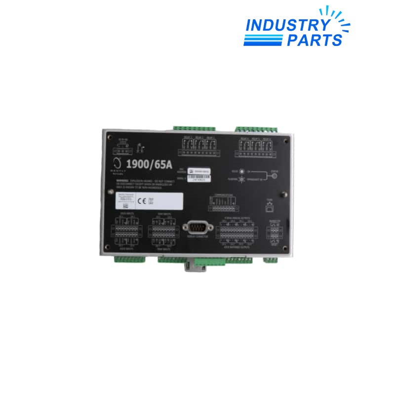
Bently Nevada 1900/65A-00-01-01-00-00 Equipment Monitor
An 18–36 VDC 1900/65A monitor with attached display, DIN-rail mounting and no communications option.
Technical Summary
1900/65A-00-01-01-00-00 combines the Bently Nevada 1900/65A monitoring platform with low-voltage DC power, an attached local display and a 35 mm DIN-rail mount. Its approval and communications fields are both set to none.
The monitor is configured in software for machinery variables, filtering, alarm setpoints, recorder signals and relay voting. The attached display supports local review without changing the need for a controlled configuration backup.
Specifications
| Manufacturer | Bently Nevada, a Baker Hughes business |
|---|---|
| Complete Model | 1900/65A-00-01-01-00-00 |
| Power Option | 18 to 36 VDC |
| Display Option | Attached display, no cable |
| Mounting Option | 35 mm DIN rail |
| Approval Option | None |
| Communications Option | None |
| Transducer Inputs | 4 configurable channels |
| Temperature Inputs | 4 channels |
| Relay Outputs | 6 |
| Recorder Outputs | 4 × 4–20 mA |
| Operating Power | 8.5 W typical; 14 W maximum |
Features
- Combines vibration and temperature processing in one configurable monitor.
- Shows variables, status and alarm information through the attached display.
- Supports relay voting and recorder-output mapping for machinery protection interfaces.
- Provides buffered transducer outputs for channel troubleshooting and signal review.
Compatibility
- Use a regulated 18–36 VDC source and retain the documented protective-ground arrangement.
- Confirm every connected transducer type, excitation method, polarity and channel scaling.
- Map each relay contact and recorder loop to the plant system before removing the installed monitor.
- Do not assume network access because the final option code does not include Modbus communications.
Replacement
- Export the complete configuration, tag names, filters, setpoints, voting logic and bypass states.
- Photograph display orientation, terminal assignments and DIN-rail clearances before disconnection.
- After installation, simulate every input and prove local indication, recorder signals, relays and final shutdown paths.
FAQ
Can 1900/65A-00-01-01-00-00 replace a version without a display?
Only after checking panel clearance, operator-access requirements and the exact mounting arrangement; the monitor database must still be transferred and validated.
What plant-network limitation applies to 1900/65A-00-01-01-00-00?
Its communications field is 00, so a requirement for Modbus data must be solved with the correctly configured monitor or project architecture.
Which records prevent a mismatched 1900/65A-00-01-01-00-00 replacement?
Provide the full option code, configuration file, sensor list, relay matrix, recorder mapping, supply details and terminal photographs.
Can the attached display be treated as the configuration backup for 1900/65A-00-01-01-00-00?
No. The display is an operator interface; maintain a separate controlled configuration file and change record.
What acceptance test is required after exchanging 1900/65A-00-01-01-00-00?
Prove channel OK states, displayed variables, alarm thresholds, bypass behavior, recorder loops, relay voting and each machine trip path.
Does 1900/65A-00-01-01-00-00 suit a classified installation?
The approval field is 00. A classified installation requires the appropriate approved execution and applicable installation drawing.
Recommended Models
| GlobTek 9000311PWRSPLY | Siemens 2KJ1304-6FP13-9HW1-Z | X20D08332 |
| 5WG1510-1AB03 | ABB RA5802/801 | MPRN01 |
| Brinkmann TH628A790-MV | DSBC-63-800-C-PPVA | Amphenol 135-2801-025 |
| MS-FEC-1610-0 | ABB DX531 / 1SAP245000R0001 | 6RA8222-1BB0-0 |
| M0PC8M45G | 251402-AP | 2160/EUI |
| DN0210 N200/SA-1 | LB 6101 GHG 127 0000 A 6101 | KJ2003X1-BA2 12P2093X112 |
| P8000A0016G | ST-CE1075-2-U100-B | 3RQ3038-1AB00 |
| 09451511140 | SP 140S-MC1-3-1K1-2K | 6AV6545-0DB10-0AX0 |
| MS 400B | K63605 | Siemens 6DS1320-8AA |
| DRVL 1000 VL-CSA-A | 1C31233G04 | Motorola PMKN4119 |


