
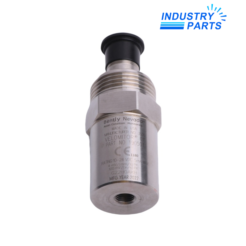

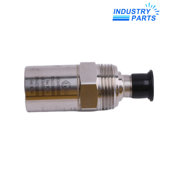
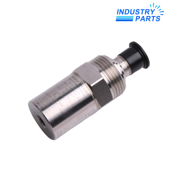
Bently Nevada 190501-09-00-04 Velomitor CT Transducer
An integrating piezoelectric velocity transducer configured with a plate stud, MIL-style connection and approval option 04.
Overview
190501-09-00-04 is a Bently Nevada Velomitor CT transducer developed for low-frequency vibration monitoring on cooling-tower and air-cooled heat-exchanger machinery. Its internal electronics convert the piezoelectric signal to a velocity output while remaining electrically isolated from the case.
The complete suffix identifies the mounting adapter, connection interface and agency-approval execution. These details must be retained together because mechanical mounting, field wiring and hazardous-area documentation affect the completed installation.
Specs
| Manufacturer | Bently Nevada, a Baker Hughes business |
|---|---|
| Model | 190501-09-00-04 |
| Product Family | Velomitor CT velocity transducers |
| Measurement Principle | Integrating piezoelectric velocity transducer |
| Sensitivity | 3.94 mV/mm/s (100 mV/in/s), ±5% |
| Frequency Response | 3 Hz to 900 Hz, ±1 dB; 1.5 Hz to 1 kHz, ±3 dB |
| Velocity Range | 63.5 mm/s peak (2.5 in/s peak) |
| Output Bias | 10.1 VDC, ±1 VDC |
| Operating Temperature | -40 °C to +85 °C |
| Storage Temperature | -40 °C to +100 °C |
| Maximum Cable Length | 305 m (1,000 ft); continuous cable available to 91.44 m (300 ft) |
| Shock Resistance | 5,000 g peak maximum |
| Humidity | 100% condensing, non-submerged |
| Mounting Option 09 | Plate stud, 3/8-24 to 1/4-in NPT |
| Connection Option 00 | MIL-C-5015 interface |
| Approval Option | 04; match the installation to the applicable certificate and area documents |
Features
- Measures casing velocity on low-speed machinery where conventional higher-frequency sensor choices may be less suitable.
- Maintains electrical isolation between sensing electronics and the transducer case to reduce ground-loop risk.
- Supports long field-cable runs when the connected monitor and installation design remain within the published limits.
- Uses a rugged sealed construction for condensing industrial environments outside submerged service.
Applications
- Cooling-tower fan and gearbox monitoring, including fans operating down to approximately 90 rpm.
- Air-cooled heat-exchanger fan trains and other low-speed rotating assets.
- Permanent casing-vibration channels connected to compatible Bently Nevada monitoring hardware.
Lifecycle
- Record the existing mounting plate, stud, connector and cable route before removal.
- Confirm the approval certificate and wiring practice for the classified area rather than relying only on the suffix.
- Prepare a clean, flat mounting surface and verify mounting torque and cable strain relief.
- After installation, confirm bias voltage, signal polarity and baseline vibration with the machine in a known condition.
FAQ
What mounting evidence should accompany an enquiry for 190501-09-00-04?
Send photographs and dimensions of the mounting plate, thread adapter, sensor orientation and available wrench clearance so the option 09 interface can be confirmed.
How should a long cable run be planned for 190501-09-00-04?
Check the connected monitor input, cable capacitance, shielding, routing and junction count as one loop; do not select the sensor only from the maximum published distance.
What does a changed bias voltage indicate after installing 190501-09-00-04?
A bias outside the expected operating window can point to wiring, connector, power-supply or transducer problems and should be resolved before vibration data is accepted.
Can 190501-09-00-04 be commissioned from a single vibration reading?
No. Establish a stable baseline at known speed and load, compare phase and neighboring points, and verify that structural looseness or mounting resonance is not dominating the measurement.
Which hazardous-area records should be retained for 190501-09-00-04?
Keep the exact sensor label, certificate revision, associated apparatus or barrier data, cable parameters and installation drawing with the maintenance file.
Recommended Models
| PM5500 METSEPM5560 | C7958-L703-A31 | Siemens, 3WL1208-3EB35-4GA2-Z |
| Imaje 721 | LV-NH42 | 4WRPEH 6C3B12L0811404608 |
| MIL-S800i | GWB 64 | W7752D2007 |
| X67BC8331 | RTCL009NAA | 13070-250 |
| 0PS1050.1 | 6ES5432-4UA11 | EPN-110DN |
| PSU100S 6EP1332-2BA20 | Siemens 6SL3330-7TE36-1AA3 | S803B100 |
| PK60-III CE/PF 116-010074H | VBA-2E-G10-ZAL-1M-2V31-G | SMC MGPM20TF-20 |
| 05-7063-JMD03S2-R0BK | ABB TU506 1SAP210000R0001 | UKH70 |
| OL5001 | 6ES7138-7EA01-0AA0 | MLD500-XT3L/A 66502601 + MLD510-XR3L/A |
| MCE101C4R70P42K0E20BAW | Honeywell DPSN400A | VG 92038143101 |