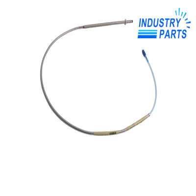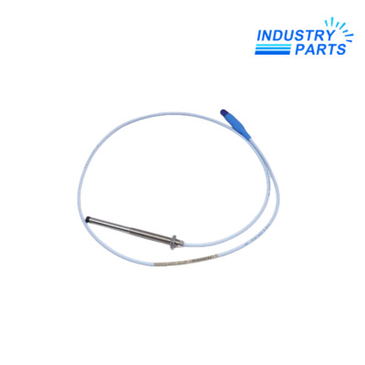


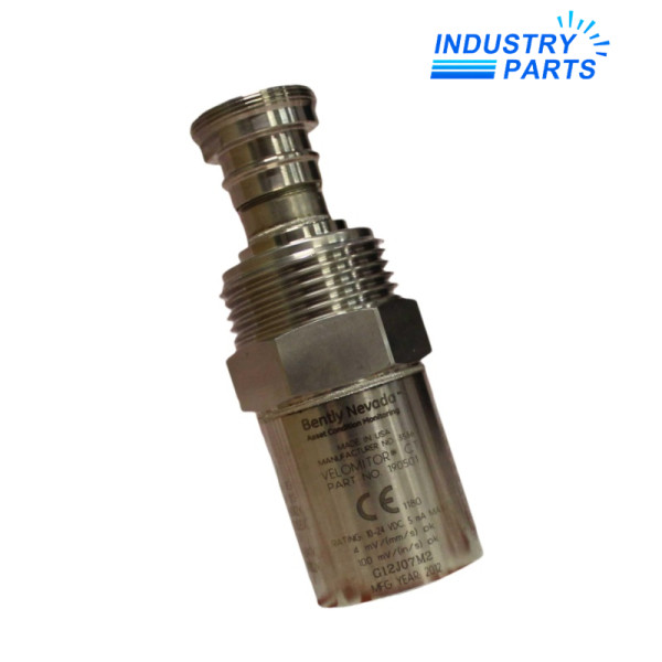
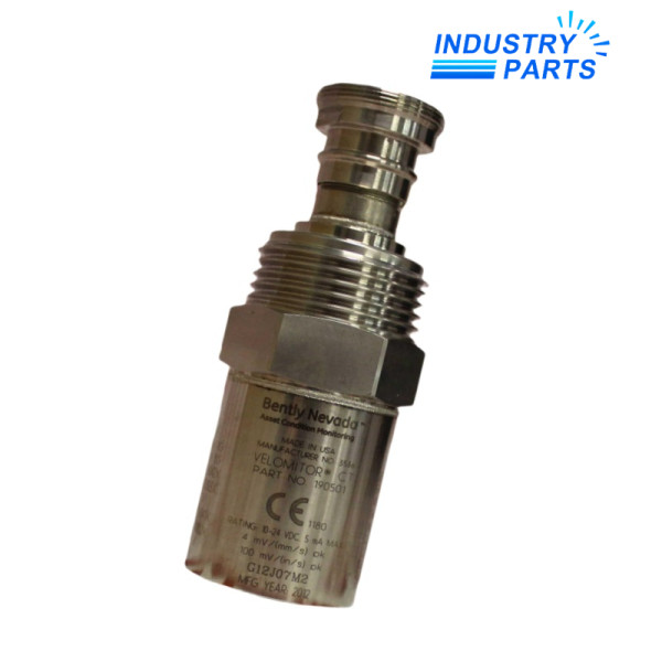
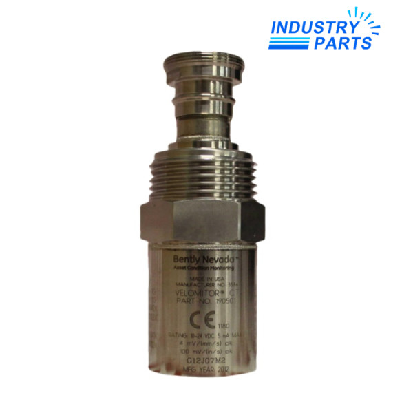
Bently Nevada 190501-21-00-01 Low-Frequency Velocity Transducer
A Velomitor CT velocity transducer configured with a 3/8-24 to 1/2-14 NPT adapter and MIL-C-5015 connection.
Key Information
190501-21-00-01 is a Bently Nevada Velomitor CT transducer. Option 21 selects the 3/8-24 to 1/2-14 NPT adapter, code 00 retains the MIL-C-5015 connection and code 01 selects the listed multi-approval execution.
The sensor produces 3.94 mV/mm/s (100 mV/in/s) with ±5% sensitivity tolerance. Its published response is 3 to 900 Hz within ±1 dB and 1.5 Hz to 1 kHz within ±3 dB.
The low-frequency response suits machinery whose vibration spectrum extends below the range of many standard velocity transducers. Mounting quality, orientation and cable routing remain part of measurement performance.
Functions
Absolute casing vibration
Measures machine-housing velocity through a self-contained Velomitor sensing element.
Low-frequency observation
Extends useful response to 1.5 Hz for slower vibration phenomena.
Integrated signal conditioning
Provides the published sensitivity without a separate external velocity converter.
Long cable support
Permits manufacturer-published cable runs up to 305 m when installed correctly.
Specifications
- Manufacturer
- Bently Nevada
- Exact model
- 190501-21-00-01
- Product family
- Velomitor CT
- Sensitivity
- 3.94 mV/mm/s (100 mV/in/s) ±5%
- Frequency response ±1 dB
- 3 to 900 Hz
- Frequency response ±3 dB
- 1.5 Hz to 1 kHz
- Velocity range
- 63.5 mm/s peak
- Linearity
- ±2%
- Transverse response
- Less than 5%
- Bias voltage
- 10.1 VDC ±1 V
- Maximum cable length
- 305 m
- Operating temperature
- −40 to +85 °C
- Mounting adapter
- 3/8-24 to 1/2-14 NPT
- Electrical connection
- MIL-C-5015

About IndustryParts
https://www.industryparts.com/Sensor configuration and mounting evidence travel together
IndustryParts handles the adapter code, connector execution, approval suffix and machinery context as one Velomitor CT supply record.
Installation
Prepare a rigid mounting point
Confirm the 1/2-14 NPT interface, surface condition and sensor orientation specified by the machine plan.
Protect the signal cable
Use the approved connector, strain relief and routing while observing the manufacturer cable-length boundary.
Establish a baseline
Record bias voltage, quiet-running value and known machine response before releasing the channel.
Lifecycle
Mounting inspection
Check adapter security, corrosion and cable strain during planned machinery inspections.
Trend continuity
Preserve sensor orientation and channel scaling so velocity trends remain comparable.
Approval trace
Keep the 01 approval suffix and complete label in the installed instrument register.
Related Models
FAQ
What mounting adapter is included with 190501-21-00-01?
Ordering code 21 selects a 3/8-24 to 1/2-14 NPT adapter.
Why is 190501-21-00-01 used on lower-speed machinery?
Its published response extends to 1.5 Hz within ±3 dB, making slower vibration content measurable.
What connector does 190501-21-00-01 use?
Connection code 00 identifies the MIL-C-5015 electrical interface.
How long can the cable run be for 190501-21-00-01?
The manufacturer publishes a maximum cable length of 305 m, subject to the complete installation requirements.
What should be recorded after installing 190501-21-00-01?
Capture mounting orientation, bias voltage, channel scaling, baseline velocity and the completed alarm or protection test.