

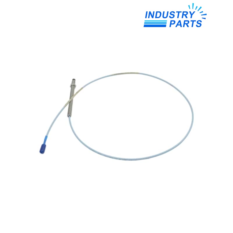
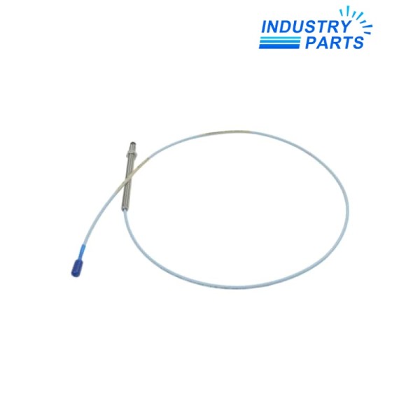
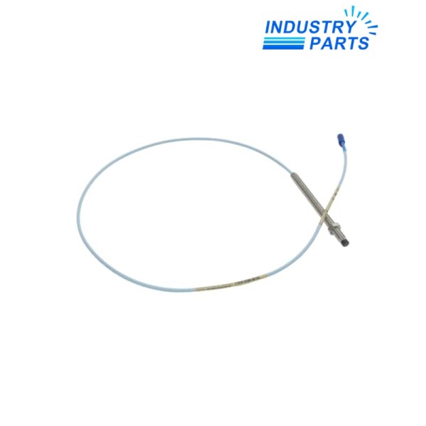
Bently Nevada 330101-00-50-05-02-00 8 mm Probe
A non-armored imperial 8 mm probe with a 5.0-inch case, short standard cable and ClickLoc connection.
Key Information
330101-00-50-05-02-00 is a Bently Nevada 3300 XL 8 mm proximity probe with 3/8-24 UNF thread and no armor. Its code specifies no unthreaded section, a 5.0-inch overall case, 0.5 m total length, a ClickLoc miniature coaxial connector without protector, standard cable and no agency approvals.
The probe is one element of a calibrated proximity transducer chain. The selected extension cable must make the probe-plus-cable length agree with the installed 3300 XL Proximitor Sensor; matching only the thread and tip diameter is insufficient.
Functions
- Detects shaft-to-probe distance without mechanical contact through an eddy-current transducer system.
- Supports relative shaft vibration, axial position and other displacement measurements within the system range.
- Fits brackets and housings designed for the imperial 3/8-24 probe body.
- Provides a serviceable ClickLoc junction to the correct extension cable.
- Uses the robust 8 mm molded probe tip for general rotating-machinery installations.
Specifications
| Manufacturer | Bently Nevada, a Baker Hughes business |
|---|---|
| Model | 330101-00-50-05-02-00 |
| Series | 3300 XL 8 mm proximity transducer system |
| Probe Thread | 3/8-24 UNF |
| Armor | Without armor |
| Unthreaded Length | 0.0 in |
| Overall Case Length | 5.0 in |
| Total Probe Length | 0.5 m (1.6 ft) |
| Connector / Cable Option | ClickLoc connector without protector; standard cable |
| Approval Option | 00, approvals not required |
| Nominal System Scale Factor | 7.87 V/mm (200 mV/mil) |
| Nominal System Linear Range | 2.0 mm (80 mil) |
| Frequency Response | 0 Hz to 10 kHz, +0/-3 dB |
| Minimum Flat Target | 15.2 mm diameter |
| Minimum / Recommended Shaft Diameter | 50.8 mm minimum; 76.2 mm recommended |
Installation
- Measure the existing case reach and locknut position so a close 4.7- or 5.2-inch variant is not substituted.
- Select an extension cable that completes the required 1 m, 5 m or 9 m system length with the 0.5 m probe lead.
- Provide suitable connector protection and strain relief because option 02 does not include the protector.
- Check target material, curvature, side-view clearance and probe-tip separation before interpreting calibration.
- Re-gap the probe and document static voltage, runout and running baseline after replacement.
Lifecycle
- Keep the probe, extension cable and Proximitor Sensor codes together in the channel record.
- Inspect the exposed non-armored lead for abrasion, oil contamination and tight bend radius.
- Do not assign hazardous-area approval to the 00 execution.
- Use controlled gap and response testing to distinguish a probe fault from cable, target or monitor problems.
FAQ
Can 330101-00-50-05-02-00 replace a nearby 330101 case-length option?
Only after the mounting bracket, insertion depth and adjustment allowance are checked; an apparently small case-length change can move the usable tip position.
How is the extension cable chosen for 330101-00-50-05-02-00?
Subtract the probe lead length from the Proximitor Sensor system length, then verify the compatible connector and cable family rather than selecting by physical reach alone.
What protection is required at the connector of 330101-00-50-05-02-00?
Use the installation-approved protector or enclosure and keep the junction clean, dry and strain-free because this connector option is supplied without a protector.
What target information should accompany a 330101-00-50-05-02-00 enquiry?
Provide target material, shaft diameter, measurement direction, nearby metal clearance and any special calibration requirement to avoid a scale-factor mismatch.
Which post-installation comparison is most useful for 330101-00-50-05-02-00?
Compare gap voltage, slow-roll waveform, runout, phase and operating vibration with the pre-maintenance channel record under similar machine conditions.


