

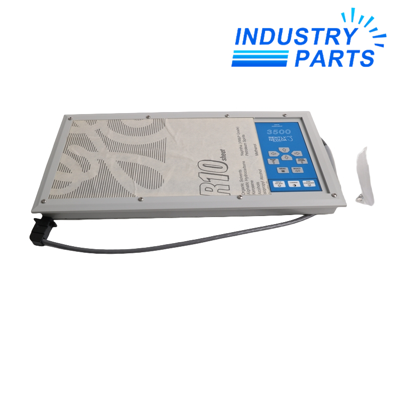



Bently Nevada 3500/93 System Display
A configurable 3500 System Display that presents rack status, channel data and event information at the machine or from a remote mounting location.
Technical Summary
Bently Nevada 3500/93 provides local or remote visual indication of information held in a 3500 machinery-protection rack, including system events, alarm events and data from monitor, relay, Keyphasor and tachometer modules.
The display is configured with 3500 Rack Configuration Software and supports face, 19-inch EIA rack, panel and independent mounting. Up to two displays may be connected to one rack, with one empty rack slot required for each corresponding Display Interface Module.
System selection includes the display style, mounting distance and cable type, external power option and agency approval. These fields define a complete display assembly and should be retained together.
Specifications
Bently Nevada
3500/93
3500 System Display
640 × 200 dots
Reflective or transflective back-lighted FSTN LCD
RS422
Bently Nevada proprietary protocol and Modbus-based display communication
1 second
15.5 W for Display Unit and Display Interface Module
−20 to +65 °C
Face, 19-inch EIA rack, panel or independent
Up to two
Features
Rack-wide information view
Presents system and alarm event lists together with channel and module information.
Visible status hierarchy
Dedicated indicators distinguish rack OK, Alert, Danger, channel state and newly detected alarms.
Flexible physical placement
Supports direct rack face mounting or remote EIA-rack, panel and independent installations.
Configuration-controlled interface
Display behavior is established through 3500 Rack Configuration Software.
Compatibility
Mounting option
Face mounting is not compatible with the 3500 mini-rack and places the DIM in slot 15.
Distance and power
Runs longer than 100 ft require the documented external supply and cable adapter; back-lighted units also require external power.
Rack capacity
Reserve one front slot for each display interface and confirm the matching rear I/O arrangement.
Display database
Preserve the accepted rack configuration and operator display selections during service.
Replacement
Capture the full order structure
Record display part number, mounting type, cable, external supply, DIM/I/O identities and approval option.
Rebuild the documented assembly
Install the matched display and interface hardware without changing the rack or cable topology.
Validate every view
Check rack and channel status, event lists, alarms, keyboard navigation, update timing and both communication indicators.
About IndustryParts
https://www.industryparts.com/Traceable handling for 3500/93
IndustryParts keeps the submitted 3500/93 identity, requested quantity and installed-system evidence together so the proposed supply can be checked before dispatch.
Exact submitted model retained
Host-system evidence reviewed
Quantity linked to the identity record

FAQ
Q01
How many 3500/93 displays can connect to one rack?
+
The manufacturer allows up to two displays, with one empty 3500 rack slot required for each corresponding Display Interface Module.
Q02
When does 3500/93 require an external power supply?
+
Back-lighted display options require it, and remote applications longer than 100 ft use the external supply and cable-adapter arrangement.
Q03
Can 3500/93 be face-mounted on a 3500 mini-rack?
+
No. The published face-mount option is not compatible with the 3500 mini-rack.
Q04
What should accompany a 3500/93 enquiry?
+
Send the complete display order code, mount type, cable length and material, external-power choice, agency approval and DIM/I/O labels.
Q05
What should be tested after 3500/93 service?
+
Verify unit, rack and channel indicators; event and alarm lists; keyboard operation; data updates; and communication with the rack.


