

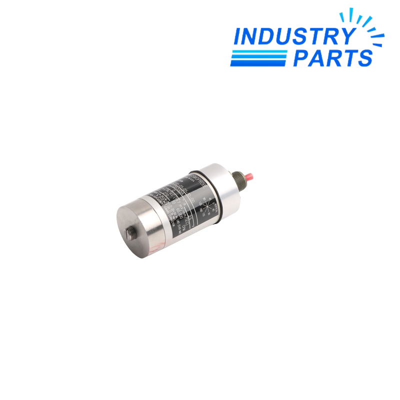


Produces a self-generated two-wire velocity signal without an external transducer power supply.
Technical Summary
9200-01-01-10-00 is a Bently Nevada two-wire Seismoprobe velocity transducer configured for a 0° ±2.5° mounting orientation and a 4.5 Hz minimum frequency.
The ordering string defines a top-mounted connector without cable, a circular base with M10 × 1 stud, and no hazardous-area approval option.
Its moving-coil output is proportional to vibration velocity and is used for machine-casing vibration measurement within the stated orientation and frequency limits.
Specifications
| Manufacturer | Bently Nevada |
|---|---|
| Exact ordering number | 9200-01-01-10-00 |
| Product family | 9200 Seismoprobe |
| Orientation code 01 | 0° ±2.5° |
| Minimum frequency | 4.5 Hz (270 cpm) |
| Connector code 01 | Top mount, no cable |
| Base code 10 | Circular base, M10 × 1 stud |
| Approval code 00 | No approvals |
| Sensitivity | 20 mV/mm/s (500 mV/in/s), ±5% |
| Calibration load | 10 kΩ |
| Upper frequency | 1 kHz |
| Dynamic operating range | 2.54 mm peak-to-peak |
| Velocity range | 25 mm/s at stated test condition |
| Coil resistance | 1.25 kΩ, ±5% |
| Coil inductance | 125 mH typical |
| Operating and storage temperature | -29 to +121 °C |
| Humidity | Up to 95% non-condensing |
| Typical height | 102 mm |
| Typical diameter | 41 mm |
| M10 × 1 mounting torque | 5.6 N·m |
| Manufacturer datasheet | Bently Nevada document 141626, revision V |
Features
Provides 500 mV/in/s nominal sensitivity for casing-vibration measurement.
Uses a top connector and defined circular M10 × 1 mounting base.
Supports operation from the 4.5 Hz option minimum through 1 kHz.
Compatibility
- Mount the transducer within 0° ±2.5° of its specified orientation.
- Confirm that the monitor input and field wiring accept the stated sensitivity and coil characteristics.
- Use the M10 × 1 base and specified torque on a clean, flat mounting surface.
- Do not use the 00 approval option where a certified hazardous-area execution is required.
Replacement
- Record orientation, base condition, cable polarity and monitor-channel settings before removal.
- Inspect the mounting face and stud, then install the transducer at the specified torque.
- Check continuity and insulation before reconnecting the monitoring channel.
- Confirm signal polarity, baseline vibration and alarm response after installation.
FAQ
What installation detail most often distinguishes 9200-01-01-10-00 from nearby variants?
Its top connector, 0° orientation and circular M10 × 1 base must all match; the model is not defined by sensitivity alone.
Can 9200-01-01-10-00 be used in a hazardous area?
The final 00 code indicates no approvals, so the site classification must not require a certified approval option.
What should be checked if the replacement signal is unusually low?
Verify mounting tightness and orientation, cable continuity, polarity, monitor sensitivity and that the vibration frequency is above the option minimum.
Should the old mounting stud automatically be reused?
Reuse only if its thread, condition and engagement are verified; damaged or mismatched hardware can distort the measurement.
What documentation should be retained after commissioning?
Keep the exact model label, mounting orientation, torque record, wiring polarity, baseline reading and alarm test result.
About IndustryParts
https://www.industryparts.com/Velocity-transducer enquiries preserve orientation and base details
IndustryParts records 9200-01-01-10-00 with its connector, mounting base and no-approval execution clearly separated from other 9200 variants.
- Exact four-part suffix retained
- Orientation and base recorded
- Monitor sensitivity evidence requested


