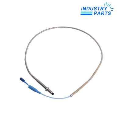

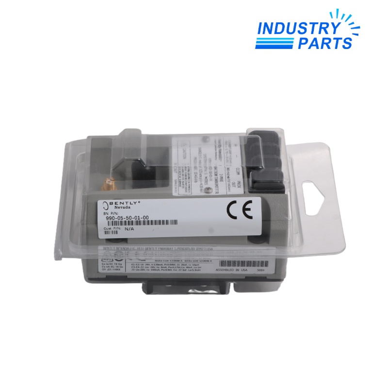

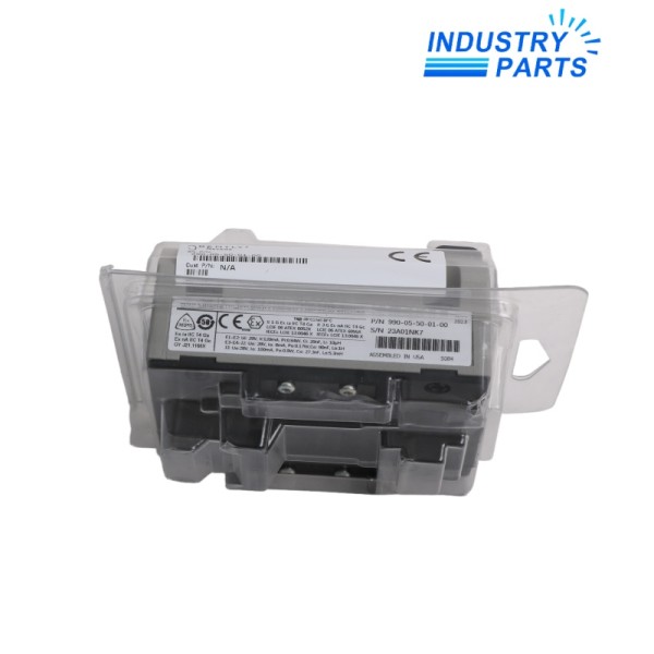

Bently Nevada 990-05-50-01-00 Vibration Transmitter
A compact DIN-mounted transmitter for a short 3300 NSv sensor chain in a non-approved installation.
Key Information
990-05-50-01-00 converts the signal from a matching 3300 NSv proximity system into a proportional two-wire current output. It is intended for machinery where a control system needs a direct vibration variable without a rack monitor.
This exact code uses the general-purpose approval execution. If the field area is classified, the application must be reviewed against a correctly approved transmitter code instead.
Functions
- Measures radial vibration through a single non-contact proximity channel.
- Supplies a standard analog signal for plant control, trending or alarm logic.
- Offers a local buffered signal for sensor-gap and dynamic-signal checks.
- Includes external zero and span adjustments for loop commissioning.
Specifications
| Manufacturer | Bently Nevada, a Baker Hughes business |
|---|---|
| Complete Model | 990-05-50-01-00 |
| Full-Scale Range | 0 to 5 mil peak-to-peak (0 to 125 µm peak-to-peak) |
| System Length | 5.0 m (16.4 ft) |
| Mounting Option | 35 mm DIN-rail clips |
| Agency Approval | Not required |
| Compatible Sensor Chain | 3300 NSv probe and extension cable |
| Loop Accuracy | ±1.5% of full scale, excluding sensor scale-factor error |
| Current Limit | 23 mA typical |
| Buffered Output Scale | 200 mV/mil (7.87 mV/µm) |
| Buffered Linear Range | 55 mil (1.4 mm) |
| Minimum Target Diameter | 9.5 mm (0.375 in) |
Installation
- Match the probe and extension-cable combination to the ordered system length.
- Mount the transmitter on a stable DIN rail and route sensor wiring away from high-energy conductors.
- Set mechanical gap first, then commission loop zero and span against the receiving input.
- Prove signal direction, channel scaling and every configured alarm before returning the machine to service.
Lifecycle
- Store the loop drawing and commissioning readings with the transmitter code.
- Do not move this general-purpose execution into a classified location without a formal protection review.
- Check the full sensor chain when drift, intermittent not-OK status or connector contamination appears.
FAQ
Is 990-05-50-01-00 suitable for a hazardous area?
Its approval suffix does not select an agency approval; use only where the complete installation permits that execution.
Can 990-05-50-01-00 use a seven-metre probe system?
No direct compatibility should be assumed because the transmitter is ordered for a specific total system length.
What causes unstable readings from 990-05-50-01-00?
Common checks include probe gap, loose connectors, damaged cable, grounding, target condition and noise coupling into the sensor run.
How is 990-05-50-01-00 connected to a PLC or DCS?
Use the documented two-wire loop polarity, adequate loop voltage and the correct analog-input scaling and resistance.
Should 990-05-50-01-00 be calibrated before installation?
Confirm the complete matched sensor chain and commission zero, span, gap and control-system scaling as an installed loop.
What should be included in a 990-05-50-01-00 request?
Provide the full code, probe and cable identities, target material, panel voltage, receiving card and machine application.