

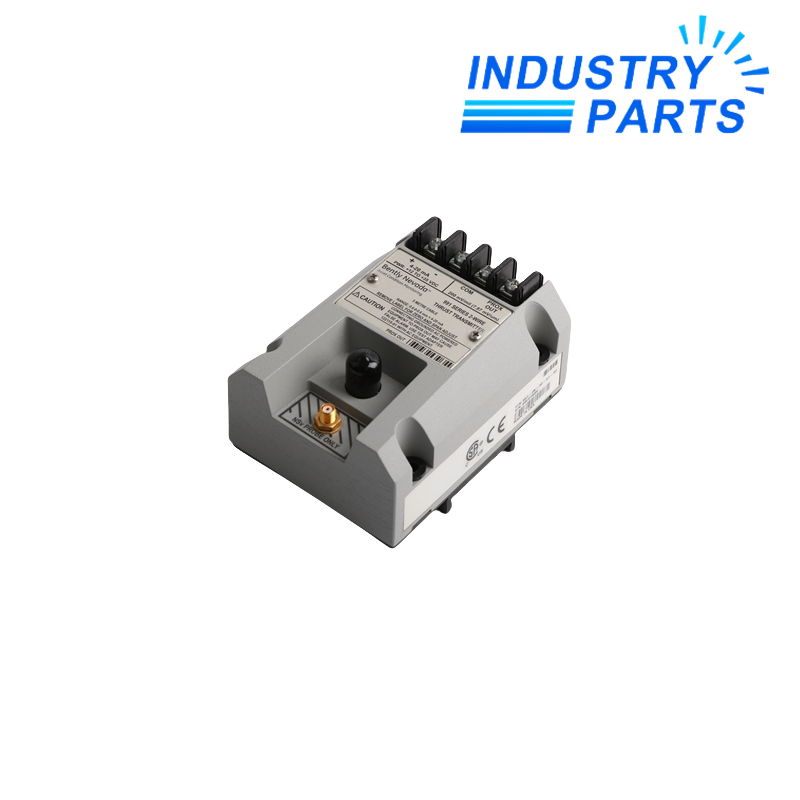
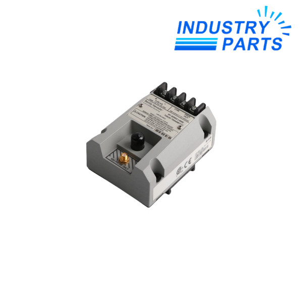

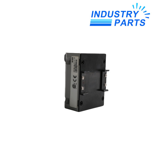
Bently Nevada 991-06-50-01-00 Thrust Transmitter
A standard metric-range axial-position transmitter for a five-metre 3300 NSv sensor system.
Technical Summary
991-06-50-01-00 is a Bently Nevada two-wire thrust transmitter that converts shaft axial position into a proportional current signal. It uses one matched 3300 NSv probe and extension cable for compact rotating-equipment installations.
The complete code selects the metric bidirectional span, shorter standard system length, DIN mounting and the general-purpose approval execution.
Specifications
| Manufacturer | Bently Nevada, a Baker Hughes business |
|---|---|
| Complete Model | 991-06-50-01-00 |
| Full-Scale Range | −0.6 to 0 to +0.6 mm |
| System Length | 5.0 m (16.4 ft) |
| Mounting Option | 35 mm DIN-rail clips |
| Approval Option | Not required |
| Input System | 3300 NSv probe and extension cable |
| Output | 4 to 20 mA DC, two-wire |
| Power Input | +12 to +35 VDC |
| Linear PROX OUT Range | 0.25 to 1.65 mm |
| Maximum Loop Resistance | 1000 Ω including cable at 35 VDC |
Features
- Provides a centered bidirectional signal for axial-position control and trending.
- Integrates Proximitor conditioning without a separate external sensor unit.
- Includes test input, zero/span adjustment and not-OK signal defeat.
- Supports a long current-loop connection between transmitter and receiving device.
Compatibility
- Use a matched five-metre 3300 NSv probe system calibrated to the target material.
- Confirm the controller interprets both normal and counter thrust directions correctly.
- Apply only in locations where the no-approval option is acceptable.
- Use an isolated test adapter with grounded AC-powered diagnostic equipment.
Replacement
- Record shaft center point, allowable travel and controller scaling before removal.
- Verify the complete probe-and-extension-cable length and mechanical gap.
- Restore zero and span only after the axial reference is established.
- Test both directions, not-OK behavior and the final trip logic.
FAQ
Can 991-06-50-01-00 use a seven-metre 3300 NSv chain?
No direct compatibility should be assumed because total system length is part of the calibrated transmitter configuration.
What controller scaling is needed for 991-06-50-01-00?
Map the current loop to a centered bidirectional axial-position variable and confirm the sign convention before enabling alarms.
Is 991-06-50-01-00 approved for a classified area?
The final 00 field does not select an agency approval; choose a certified execution when the installation requires one.
Why should 991-06-50-01-00 zero be checked after bearing work?
Mechanical changes can shift the rotor reference, so the transmitter center and protection thresholds must be revalidated.
What should be tested after replacing 991-06-50-01-00?
Move or simulate both axial directions, verify span and zero, test not-OK handling and prove the controller’s active protection logic.
What information should accompany a 991-06-50-01-00 quotation?
Send probe and cable labels, target material, existing gap, controller scaling, mounting details and site classification.
Recommended Models
| M132s4 | EL6201 | MCE3 |
| 3RU2146-4HB0 | SYSTIMAX 760028373 | Schneider MTN649202 |
| ASH 84 CFN5 Type 036.084.1 | 1LA7133-4AA90ZN05 | 6ES5757-0AA11 |
| KA19B CMP50S/BK/KY/AK0H/SB1 | SV9344.150 | V100 |
| INK0572-00-31-41/03 | 6RA2281-6GV62-0 | Rexroth MHD112C-058-NP3-AN |
| Cow KMA 9702 | KE300 LT303 SE301 VM300 | GTH53-2411-A1F1-2Q |
| DF103V | FDAI92EX | Beckhoff LC5200 |
| ABB 2CDG 110 167 R0011 | 3DM580 | D0479 |
| VLT 3002 175H7238 | Feb-00 | 21X25-RS0B0-Z0H0-ST5S00N-R0SU |
| 3842517623 EQ 2/E | MTL5074 | D-M9PA |


