

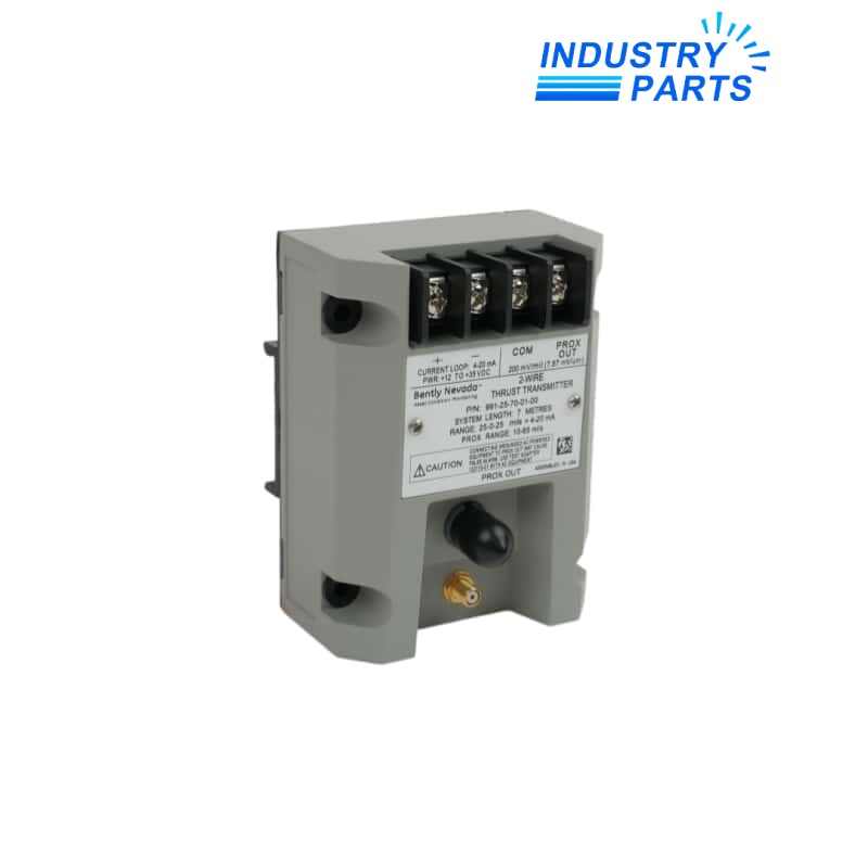
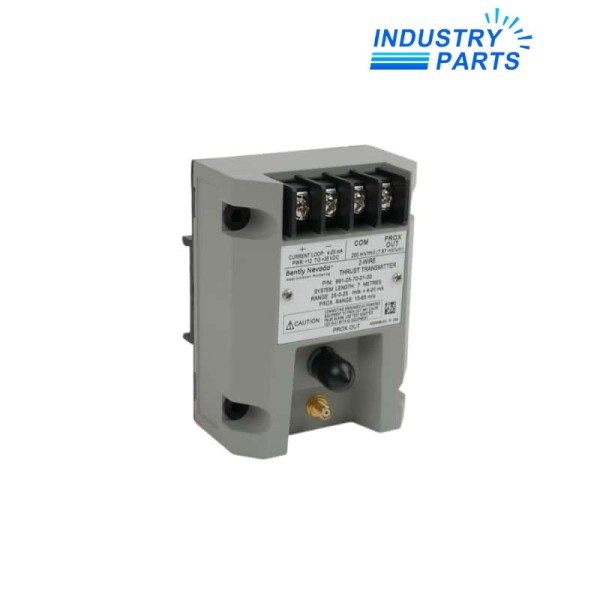
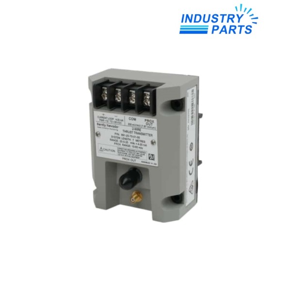
Bently Nevada 991-25-70-01-01 CSA Thrust Transmitter
A 7 m axial-position transmitter with DIN-rail mounting and the CSA Division 2 approval selection.
Overview
991-25-70-01-01 shares the 25-0-25 mil measuring range and 7 m NSv system length of the standard 991 execution, while its final ordering field selects CSA Division 2 approval.
The unit delivers a loop-powered 4–20 mA output and retains a buffered diagnostic connection for commissioning and troubleshooting.
Specs
| Manufacturer | Bently Nevada, a Baker Hughes business |
|---|---|
| Complete Model | 991-25-70-01-01 |
| Measurement Range | 25-0-25 mils |
| System Length | 7.0 m |
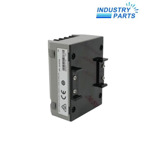
| Mounting Option | 35 mm DIN-rail clips |
| Approval Selection | CSA Division 2 |
| Transmitter Circuit | Two-wire, loop powered |
| Supply Requirement | 12 to 35 V DC |
| Typical Loop Accuracy | ±1.5% of full scale |
| Maximum Loop Resistance | 1000 ohms at 35 V |
Features
- Integrated signal conditioning eliminates a separate external Proximitor Sensor.
- Not OK behavior can drive loop current below 3.6 mA for fast fault recognition.
- Zero and span potentiometers support commissioning of the selected thrust range.
- Potted construction is suitable for condensing humidity when installed as specified.
Applications
- Approved axial-position loops in OEM compressor and pump packages.
- Motor or fan thrust monitoring where CSA Division 2 documentation is required.
- Control-system integration through a standard analog current input.
Lifecycle
- Keep the CSA records and loop drawing with the transmitter identity.
- Verify enclosure, wiring method, barriers and field devices against the classified-area design.
- Retain the full 7 m matched probe-and-cable arrangement.
- Revalidate calibration and fault-current response before returning protection logic to service.
FAQ
Can 991-25-70-01-01 be replaced by the 991-25-70-01-00?
Not in an installation that depends on CSA Division 2 approval; the 00 execution does not carry the same approval selection.
Does 991-25-70-01-01 approval cover the entire measurement loop automatically?
No. Probe, cable, enclosure, wiring practice, barriers and the final installation must all comply with the site design.
What transducer chain is required for 991-25-70-01-01?
Use the documented 3300 NSv probe and extension cable whose combined length equals 7 m.
What should purchasing preserve when ordering 991-25-70-01-01?
Preserve every suffix field and request the applicable approval documentation with the supplied unit.
Which commissioning result is most useful for 991-25-70-01-01?
A signed record of physical gap, calibrated span, loop current, fault response and receiving-channel scaling provides a strong baseline.
Can 991-25-70-01-01 be recalibrated to a metric range in the field?
Do not treat recalibration as a substitute for the correctly ordered range; use the exact transmitter execution required by the loop.
Recommended Models
| ESSER 804868 | A2V915HDHP1E00PKH170 | SXWASPXXX10001 |
| A64BTL BD627A162G53 | 6GK7243-1JX30-0XE0 | AC-VQ1051D |
| NSYCR55WU2 | ABB RXSF1-110 RK 271016-AN | CDH4U5-B |
| 1U8865 | MCR-SL-S-1/5-I-DCI-24 | MFP32D/Z23D |
| YF-509 | SA57/T DRN100LM4/BE5/IS/TF | 46B/44-S12 |
| A05B-2400-C061 | Oct-12 | GEHRING 098982 |
| D2130 | X67BCE321.L12 | D-1101-RSG2100 RJ45TX01 |
| 371-03638-000 | Festo DGE-40-600-ZR-LH-RK-KF-GV 193743 | TWDLMDA20DTK |
| AC1305 | R165111420 KWD-015-FNS-C1-N-1 | YSS7116 |
| TA-BL-30/4Q | DSC LC-200S | OAC808.9-1 |


