

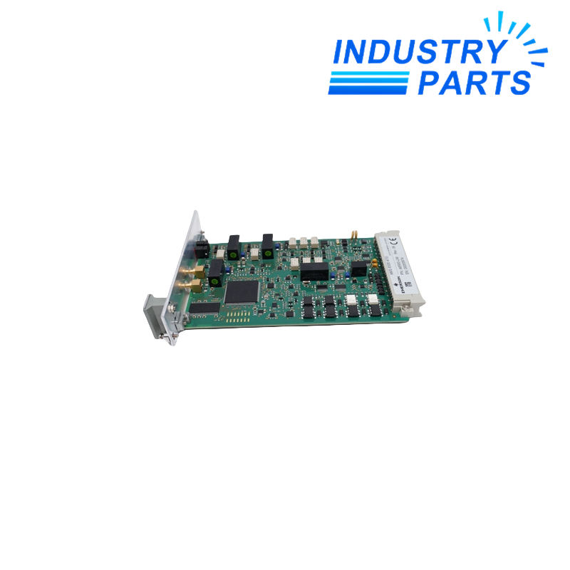


Processes shaft and case vibration, position, eccentricity, speed, key and dynamic-pressure measurements.
Key Information
A6500-UM is a two-channel universal measurement card for the AMS 6500 ATG machinery protection system. Its two sensor channels can operate independently or together according to the selected measurement mode.
A6500-UM accepts common eddy-current, piezoelectric, electro-dynamic, low-frequency bearing-vibration, Hall-effect, LVDT with A6500-LC, and dynamic-pressure sensor paths.
Functions
Provides front and rear buffered signals together with two configurable 0/4-20 mA current outputs.
Communicates measured values through the internal RS-485 bus to an A6500-CC communication card for Modbus RTU or Modbus TCP/IP integration.
Supervises hardware, supply, module temperature, sensor and cable conditions through built-in self-checking functions.
Specifications
| Manufacturer | Emerson |
|---|---|
| System | AMS 6500 ATG |
| Form factor | 3U, one-slot plug-in card |
| Measurement channels | 2, independent or combined by mode |
| Digital inputs | 5 |
| Key-signal inputs | 2 of the 5 digital inputs; DI1 or DI2 |
| Key-signal frequency | 0 to 2000 Hz at 20-80% duty cycle |
| Current outputs | 2, configurable 0/4-20 mA |
| Current-output load | Less than 500 ohms |
| Digital outputs | 6 normally-open solid-state relays |
| Digital-output supply | 19 to 32 VDC, 100 mA maximum load |
| Eddy-current input range | -1 to -22 V |
| Eddy-current frequency range | 0 to 18,750 Hz |
| Sensor supply | Selectable -23.25 or -26.0 VDC, short-circuit protected |
| Operating temperature | -20 to +70 degrees C |
| Rack | A6500-xR system rack |
| Service feature | API 670 compliant and hot swappable |
Installation
- Confirm rack, rear terminal assignment, sensor type and channel mode in the approved AMS 6500 configuration before insertion.
- Keep buffered, proportional, digital and communication wiring separated according to the rack documentation.
- After replacement, download or verify the channel configuration and confirm sensor-bias, OK state, alarm logic and output scaling.
- Use the system hot-swap procedure; hot-swappable construction does not remove the need to manage bypass and trip voting.
Lifecycle
- Archive the card configuration, firmware identity, rack slot and channel calibration with the machine record.
- Trend sensor-bias and self-check diagnostics so cable or transducer degradation is not mistaken for a card fault.
- When planning a spare, verify rear terminal, communication-card and rack compatibility as one protection-system path.
About IndustryParts
https://www.industryparts.com/Protection-card data stays tied to the machine record
IndustryParts prepares A6500-UM supply around the rack slot, sensor path and retained configuration rather than the card number alone.
- Rack identity recorded
- Sensor path checked
- Configuration evidence retained

FAQ
What configuration files should accompany an A6500-UM spare?
Keep the exported rack configuration, channel modes, transducer types, alarm delays, voting logic and proportional-output scaling with the spare record.
Can A6500-UM be hot swapped without affecting machine protection?
The card supports hot swapping, but the affected channels and trip logic must first be placed in the approved bypass or maintenance state.
How should A6500-UM sensor compatibility be confirmed?
Match the exact sensor technology, supply, bias range, sensitivity and wiring path, including A6500-LC where an LVDT application uses it.
What should be verified after installing A6500-UM?
Check rack recognition, channel OK status, live values, buffered signals, relay logic and both current outputs before returning protection to service.
What distinguishes an A6500-UM card problem from a field problem?
Compare sensor bias, cable checks, buffered signal and channel diagnostics across the field path before attributing a fault to the card.


