

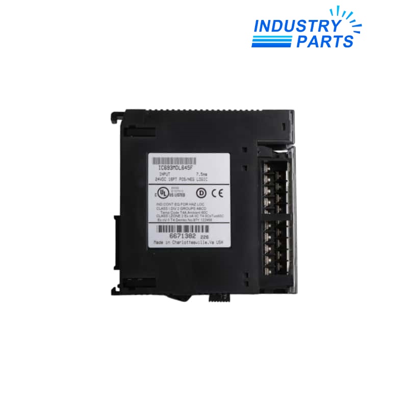

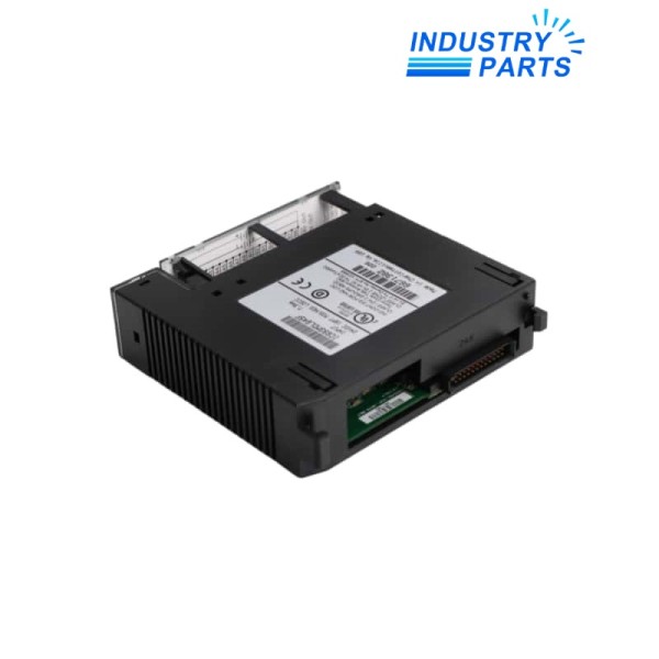
Emerson IC693MDL645F Series 90-30 DC Input Module
A 24 VDC Series 90-30 input module requiring the field polarity, group wiring and F revision to be verified as one selection record.
Key Information
IC693MDL645F accepts sixteen 24 VDC discrete input signals and supports positive- or negative-logic field arrangements documented for the installed machine.
The revision F suffix does not describe the field wiring by itself. The two eight-point groups, commons, sensor supply and PLC address map must be captured from the actual panel.
Functions
Discrete state acquisition
Transfers sixteen field-device states into the Series 90-30 input image for use by the controller program.
Polarity flexibility
Accommodates positive- or negative-logic DC wiring when the group commons and field supply are connected correctly.
Grouped troubleshooting
Organizes the terminals as two eight-point groups, helping maintenance isolate common or supply faults from single-channel faults.
Status observation
Channel indicators provide local state evidence that can be compared with field voltage and the PLC input table.
Specifications
| Manufacturer | Emerson / GE Fanuc | Exact model | IC693MDL645F |
|---|---|---|---|
| Product family | Series 90-30 | Input points | 16 discrete inputs |
| Nominal input | 24 VDC | Logic support | Positive or negative logic |
| Terminal grouping | Two groups of eight inputs | Field interface | Optically coupled input circuits |
| Channel indication | Individual input-status LEDs | Installation | Series 90-30 five- or ten-slot baseplate I/O position |
| Revision identity | F suffix retained | Documentation basis | Series 90-30 I/O module specification |
Installation
Survey
Record the baseplate slot, PLC address, A- and B-group terminals, common polarity and field-supply source.
Wire
Transfer one conductor at a time under the approved isolation plan and keep sourcing or sinking logic consistent with the documented circuit.
Validate
Simulate all sixteen devices and compare terminal voltage, front indication and input-table state for each channel.
Lifecycle
Baseline
Store the complete IC693MDL645F label, wiring diagram and I/O assignment with the machine project.
Diagnose
Use group behavior, field voltage and PLC state together; an indicator alone does not prove the external circuit is healthy.
Document
Update channel test results, common polarity and any approved wiring correction before returning the input group to service.
About IndustryParts
https://www.industryparts.com/Traceable handling for IC693MDL645F
IndustryParts keeps the complete product identity, requested quantity, application record and delivery requirements together for a controlled supply review.

FAQ
What must be supplied with an IC693MDL645F enquiry?
Include the complete revision label, baseplate and slot, I/O address, field voltage, common polarity and the sixteen-channel wiring schedule.
Can IC693MDL645F be wired for either positive or negative logic?
Yes, but the installed field devices, group commons and supply polarity must follow one documented arrangement rather than being inferred from the module name.
What should be examined when eight IC693MDL645F channels change together?
Check the affected group common, field supply and terminal block before treating the event as eight independent input failures.
Does an illuminated IC693MDL645F LED prove the complete loop is correct?
No. Compare the indicator with measured terminal voltage, the PLC input table and the expected device state.
How should IC693MDL645F be accepted after replacement?
Exercise every input, verify channel mapping and polarity, confirm stable PLC states and attach the completed test sheet to the I/O record.


