

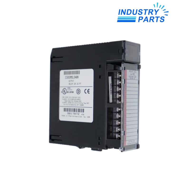

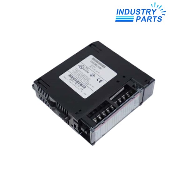

Emerson IC693MDL940H Series 90-30 Relay Output Module
A Series 90-30 relay module whose H revision and four-group output arrangement must remain visible through replacement.
Key Information
IC693MDL940H provides sixteen normally-open relay outputs arranged as four groups of four with one common connection for each group.
Its relay contacts can serve AC or DC loads within the published limits. The exact H revision, branch protection, common wiring and connected-load characteristics belong in the replacement record.
Functions
Isolated contact switching
Uses relay contacts to switch field loads without imposing a single shared common across all sixteen points.
Grouped field distribution
Separates the outputs into four four-point banks so each group common can be documented and protected.
Mixed-load flexibility
Supports suitable AC or DC field circuits when contact ratings, inrush and suppression are engineered correctly.
Visible point status
Front indicators support channel-level service checks while the controlled program remains the authoritative command record.
Specifications
| Manufacturer | Emerson / GE Fanuc | Exact model | IC693MDL940H |
|---|---|---|---|
| Product family | Series 90-30 | Output points | 16 normally-open relay outputs |
| Grouping | Four groups of four; one common per group | Nominal voltage | 24 VDC or 120/240 VAC |
| Operating range | 5–30 VDC; 5–250 VAC, 50/60 Hz | Maximum load | 2 A pilot duty per output |
| Maximum common current | 4 A per common | Minimum load | 10 mA |
| Maximum inrush | 5 A | Switching time | 15 ms maximum on or off |
| Isolation to logic | 1500 V | Isolation between groups | 500 V |
| Onboard fuses | None | Installation | Series 90-30 five- or ten-slot baseplate I/O position |
Installation
Document
Label all sixteen field conductors, four commons, load voltages and external fuses before the terminal assembly is disturbed.
Protect
Check steady and inrush current, suppression for inductive loads, conductor condition and branch protection against the approved design.
Test
Command each point separately and verify the correct load state without cross-feeding between output groups.
Lifecycle
Identify
Retain the complete IC693MDL940H revision H label and terminal map in the maintenance record.
Trend
Investigate slow operation, welded contacts, chatter or heat as field-load and contact-condition evidence.
Close out
Record point-by-point switching results, group-common voltage and protective-device status after replacement.
About IndustryParts
https://www.industryparts.com/Traceable handling for IC693MDL940H
IndustryParts keeps the complete product identity, requested quantity, application record and delivery requirements together for a controlled supply review.

FAQ
Why must the H suffix remain attached to IC693MDL940H?
It is part of the installed hardware identity. Interchange with another revision should follow the approved change process rather than visual similarity alone.
What should be checked if four IC693MDL940H outputs fail together?
Trace the affected group common, field supply, external fuse and terminal wiring before concluding that four relay channels failed simultaneously.
How should inductive loads connected to IC693MDL940H be handled?
Use suppression suited to the AC or DC load and document inrush and switching frequency so relay-contact stress remains controlled.
Does IC693MDL940H provide individual output fuses?
No. External branch and load protection must be verified against the field design and the published relay limits.
What proves an IC693MDL940H replacement is complete?
A point-by-point command test, correct load response, stable commons, verified protection and an updated terminal record complete the service evidence.


