

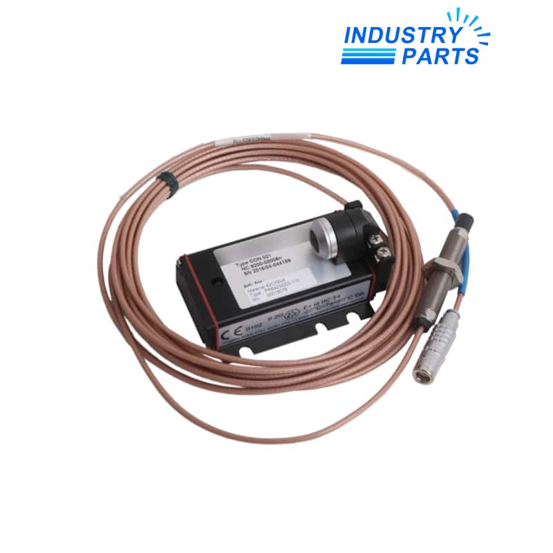


Epro PR6423/003-110 CON021 Eddy Current Sensor
A revision-specific PR6423 eddy-current probe for non-contact radial and axial shaft displacement measurement in a matched converter system.
Key Information
PR6423/003-110 is an exact orderable configuration within the Emerson EPRO PR6423 eddy-current displacement sensor family. PR6423 sensors are used for non-contact measurement of shaft vibration, eccentricity, axial position, differential expansion, valve position and air gaps.
The PR6423 family is paired with a compatible converter such as CON021. The submitted /003-110 suffix must remain complete because probe geometry, cable and termination selections are encoded in the order identity; those details should be confirmed from the probe label and installation record rather than inferred from appearance.
Functions
- Measures static and dynamic shaft displacement without contacting the rotor.
- Supports radial vibration, axial position, eccentricity and differential-expansion applications.
- Operates as the sensing element of a calibrated probe, cable and converter chain.
- Provides a standard PR6423 measuring range of 2.0 mm when used with the matching standard-range CON021 configuration.
- Supports machinery-protection installations governed by the documented probe and converter system limits.
Specifications
| Manufacturer | Emerson / EPRO |
|---|---|
| Model | PR6423/003-110 |
| Sensor Family | PR6423 |
| Product Type | Non-contact eddy-current displacement sensor |
| Nominal Probe Diameter | 8 mm family |
| Standard Measuring Range | 2.0 mm with matching standard-range CON021 |
| Standard System Linearity | ≤1.0% for PR6423 with CON021 standard-range configuration |
| Measured Variables | Radial/axial displacement, shaft vibration, eccentricity, differential expansion, position and air gap |
| Target Material | Electrically conducting steel; calibration is target-material dependent |
| Converter Family | CON021 and other documented PR6423-compatible converters |
| System Principle | Matched probe, cable and signal-converter chain |
| Applicable Standards | DIN 45670, ISO 10817-1 and API 670 referenced by the manufacturer |
| Order-Code Control | Retain /003-110 exactly; verify sleeve, thread, cable and connector from label documentation |
| Calibration Control | Probe, cable length, target material and converter must be treated as one measurement system |
Installation
- Record the full PR6423/003-110 probe label, mounting thread, sleeve dimensions, cable routing, connector and installed converter before removal.
- Measure and document the mechanical gap and shaft target condition with the machine in the approved maintenance state.
- Do not shorten, extend or substitute the probe cable unless the complete calibrated system permits that configuration.
- Route the cable away from high-energy conductors, protect the connector and observe the minimum bend and mounting clearances in the system documentation.
- After installation, prove gap voltage, linear response, channel polarity, alarm setpoints and trip logic through the complete monitoring chain.
Lifecycle
- Keep the PR6423/003-110 suffix and converter identity together in the asset record.
- Trend gap voltage and calibration results so mechanical movement is not confused with sensor or cable deterioration.
- Inspect the probe tip, sleeve, connector, cable armor and routing during planned outages.
- Replace or recalibrate the complete chain when target material, cable length or converter type changes.
FAQ
What information is needed to quote PR6423/003-110 correctly?
Send the complete PR6423/003-110 label, thread and sleeve measurements, total cable arrangement, converter model, target material, gap record and connector photographs.
Can PR6423/003-110 be paired with any CON021 found in stock?
No. Confirm that the converter calibration and range are for the PR6423 system and that the existing cable and target material match the intended measurement chain.
Should a PR6423/003-110 spare be calibrated before installation?
Yes. Acceptance should confirm the probe, cable and converter response against the actual target material or the approved calibration standard before the protection channel is released.
What usually causes a PR6423/003-110 reading shift after replacement?
Common causes include a changed mechanical gap, different target metallurgy, cable-length mismatch, connector damage, incorrect converter range or altered grounding and routing.
What commissioning evidence should accompany PR6423/003-110?
Retain the label, mechanical gap, static calibration curve, gap voltage, converter identity, cable record, alarm/trip test and final channel polarity.


