

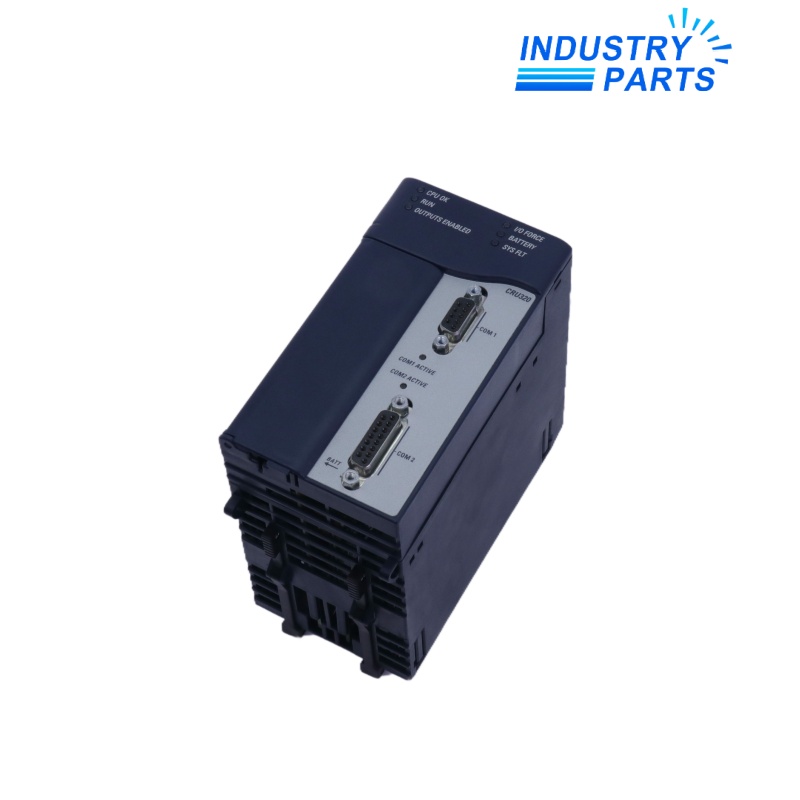


Emerson IC695CRU320 RX3i Redundancy CPU
A 64 MB RX3i hot-standby processor with ECC memory, fast switchover and support for two RMX redundancy links.
Key Information
IC695CRU320 is the PACSystems RX3i processor designed for hot-standby CPU redundancy. Manufacturer product information identifies 64 MB of battery-backed RAM, 64 MB of non-volatile flash user memory and error-correcting memory support.
The controller exchanges as much as 2 MB of reference and symbolic data in its redundancy transfer list. It supports up to two IC695RMX128 or IC695RMX228 synchronization links, with documented switchover of no more than one logic scan and a minimum of 3.133 ms.
Functions
- Executes the primary or backup role in an RX3i hot-standby controller pair.
- Synchronizes selected reference and symbolic data over RMX redundancy links.
- Corrects single-bit memory errors and checks multiple-bit memory errors.
- Provides embedded RS-232 and RS-485 communications for supported serial services.
- Maintains the approved application and state data needed for controlled switchover.
Specifications
| Manufacturer | Emerson / GE Intelligent Platforms |
|---|---|
| Model | IC695CRU320 |
| Product Family | PACSystems RX3i |
| Product Type | Hot-standby redundancy CPU |
| Program Storage | Up to 64 MB battery-backed RAM |
| Non-Volatile User Memory | 64 MB flash |
| Memory Protection | ECC: single-bit correction and multiple-bit checking |
| Program Blocks | Up to 512; 128 KB maximum per block |
| Discrete References | 32 Kbits each for %I and %Q |
| Analog References | Configurable up to 32 Kwords each for %AI and %AQ |
| Redundancy Transfer List | Up to 2 MB |
| Redundancy Links | Up to two IC695RMX128/228 links |
| Switchover Time | Maximum one logic scan; minimum 3.133 ms |
| Embedded Communications | RS-232 and RS-485 |
| Serial Protocols | Modbus RTU Slave, SNP and Serial I/O |
| Power Requirement | 1.0 A at 3.3 VDC; 1.2 A at 5 VDC nominal |
| Operating Temperature | 0 to 60 °C |
| Revision Control | Match both CPUs, firmware, RMX modules and synchronization topology |
Installation
- Export the project, transfer list, redundancy configuration, firmware matrix, fault tables and network settings from both controllers.
- Record the complete IC695CRU320 labels, active/backup roles, rack hardware and both RMX link paths.
- Place the process in the approved redundancy maintenance state before removing a CPU.
- Match firmware and configuration, then allow the replacement controller to synchronize without bypassing diagnostics.
- Prove primary/backup health, transfer-list integrity, both links and an approved switchover test before closing the work.
Lifecycle
- Trend ECC, synchronization, link and switchover diagnostics across both IC695CRU320 controllers.
- Keep paired CPU firmware, RMX firmware and project checksums under one change-control record.
- Maintain a recovery package for each rack and document which controller last held the active role.
- Test redundancy on the site schedule without turning the production system into an uncontrolled single point of failure.
FAQ
What should be matched across an IC695CRU320 redundant pair?
Match complete CPU suffixes, firmware, rack and power hardware, project and transfer list, RMX modules, fiber topology and all communication-module revisions.
Can an IC695CRU320 be changed while the partner CPU remains active?
Only under the approved hot-standby maintenance procedure after confirming partner health, current synchronization, process risk and a recovery path.
How much data can IC695CRU320 synchronize to its backup?
The documented redundancy transfer list supports up to 2 MB; the project must deliberately select and validate the required reference and symbolic data.
What acceptance test matters most after an IC695CRU320 exchange?
After synchronization and diagnostic checks, perform the site-approved switchover test and verify that control, outputs, communications and retained process state remain correct.
Why should two RMX links be documented separately for IC695CRU320?
Each path has its own module, fiber route and diagnostic state; identifying both prevents a latent single-link fault from being hidden by the healthy path.


