

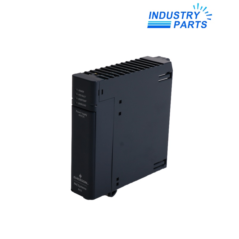


Emerson IC695PSD140 RX3i Power Supply
A one-slot 24 VDC, 40 W multipurpose RX3i backplane supply designed for load sharing and redundant power configurations.
Key Information
IC695PSD140 is a PACSystems RX3i multipurpose power supply for an IC695 Universal Backplane. It accepts a nominal 24 VDC source over an 18–30 VDC range and provides a total 40 W load capacity.
The supply can operate as the only backplane supply or participate in documented load-sharing and redundancy arrangements. It has no input-to-backplane isolation, so the plant power and grounding design must account for that boundary.
Functions
- Powers RX3i backplane electronics from a 24 VDC plant supply.
- Supports load sharing and redundant-source architectures with matching multipurpose supplies.
- Reports power, power-supply fault, overload and overtemperature conditions through front LEDs.
- Provides the +5.1 V, +3.3 V and relay-power outputs required by supported backplane modules.
Specifications
| Manufacturer | Emerson / GE Intelligent Platforms |
|---|---|
| Model | IC695PSD140 |
| Product Family | PACSystems RX3i |
| Compatibility | IC695 Universal Backplane |
| Slot Width | 1 slot |
| Nominal Input | 24 VDC |
| Operating Input Range | 18–30 VDC |
| Total Load Capacity | 40 W |
| Input-to-Backplane Isolation | None |
| Load Sharing / Redundancy | Supported |
| Maximum Multipurpose Supplies | Up to four in the documented backplane architecture |
| Wiring | 14–22 AWG, one wire per terminal |
| LEDs | Power, P/S Fault, Overload, Overtemperature |
| Operating Temperature | 0 to 60 °C at the inlet |
| Storage Temperature | -40 to +85 °C |
| Humidity | 5–95%, non-condensing |
| Conformal-Coated Option | IC695PSD140CA |
| Low-Temperature Option | IC695PSD140LT |
Installation
- Calculate the backplane load and redundant-source behavior before selecting the quantity of supplies.
- Wire the 18–30 VDC source with the specified conductor range and verified polarity.
- Keep incompatible RX3i supply types out of increased-capacity or redundant groups.
- Commission by checking every LED state, backplane load and the intended source-failure transfer.
Lifecycle
- Inspect terminal torque, ventilation and overload/overtemperature history during maintenance.
- Record the complete revision letter because release changes can affect certification or manufacturing history.
- Retain the redundancy diagram and load calculation with the cabinet documentation.
FAQ
How should a redundant IC695PSD140 group be specified in an RFQ?
State the backplane, total calculated load, number of supplies, independent power sources, external switching arrangement and required revision/option suffix.
Which RX3i supplies should not be mixed with IC695PSD140 in load-sharing mode?
Do not build the redundant or increased-capacity group from incompatible PSD040 or PSA040 types; use the approved multipurpose-supply architecture.
What does the lack of input isolation mean for IC695PSD140 installation?
The 24 VDC source, grounding and fault-clearing design must be engineered as part of the same electrical domain rather than assuming galvanic separation in the module.
How can overload and overtemperature alarms on IC695PSD140 be separated?
Capture the specific front LED, measure backplane demand and inlet temperature, then inspect airflow and individual module loads before replacing the supply.
What information distinguishes IC695PSD140 from IC695PSD140E?
IC695PSD140 is the base catalog number, while the trailing E identifies a 2016 hardware release; state whether the purchase requires that exact revision.


