

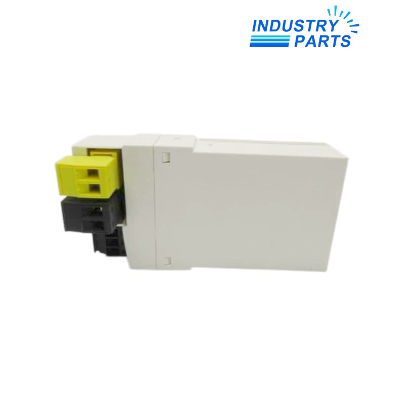
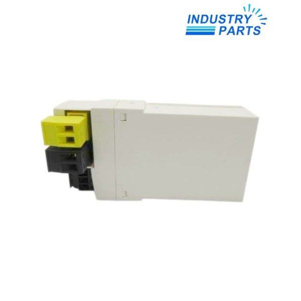
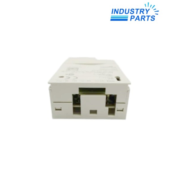
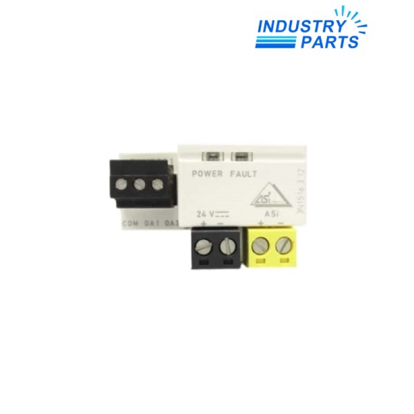
Schneider Electric ASILUFC51 Extended AS-Interface Communication Module
An extended AS-Interface communication module for networked TeSys Ultra starter-controllers.
Overview
ASILUFC51 links a compatible TeSys Ultra starter-controller to the AS-i wiring system for direct or remote control. Local indication and bus diagnostics support installation and service work.
Correct operation depends on the specified power-base, control-unit and auxiliary-supply architecture.
Specs
| Manufacturer | Schneider Electric |
|---|---|
| Model | ASILUFC51 |
| Product Family | TeSys Ultra |
| Module Type | Extended AS-Interface communication module |
| AS-i Profile | 7.A.7.E |
| Maximum Devices with Applicable Profile | 62 server devices |
| Auxiliary Supply | 24 VDC |
| Compatible Control Units | LUC••BL 24 VDC |
| Compatible Power Bases | LUB•• and LU2B•• |
| Typical AS-i Bus Current | 15 mA |
| Local Indication | Green PWR and red FAULT LEDs |
| Configuration Environment | EcoStruxure Control Expert with supported PLC interface |
Features
- Transfers run commands and starter status through AS-Interface.
- Supports remote or local diagnostics for bus and addressing conditions.
- Continuously monitors module operation with transparent self-tests.
- Front indicators distinguish bus-voltage presence from communication or auxiliary-supply faults.
Applications
- Networked TeSys Ultra motor starters in industrial automation systems.
- Starter replacement or expansion on an established AS-i segment.
- Remote status and control integration where the documented AS-i profile is supported.
Lifecycle
- De-energize the starter assembly and observe electrostatic precautions before installation.
- Confirm the 24 V DC control-unit version and power-base wiring.
- Record AS-i address, PLC configuration and external stop circuitry.
- Test local controls, network commands, feedback and protective trip behavior after commissioning.
FAQ
Can ASILUFC51 be installed with any TeSys U control unit?
No. Schneider specifies compatible LUC••BL 24 VDC control units and the appropriate LUB or LU2B power base.
What must be preserved when replacing ASILUFC51?
Record the AS-i address, selected profile, PLC configuration, auxiliary supply and any direct-wired stop circuit.
How does ASILUFC51 support a larger AS-i segment?
Its 7.A.7.E motor-start profile supports the extended addressing arrangement used for up to 62 server devices when the client interface is configured accordingly.
What do the LEDs on ASILUFC51 help diagnose?
They identify AS-i bus-voltage presence and fault conditions such as lost communication, incorrect addressing or missing auxiliary voltage.
Can ASILUFC51 network data be used for an emergency stop?
No. Schneider states that communication ports carry non-critical data and critical safety functions require the appropriate hardwired safety architecture.
Which wiring accessory details should accompany an ASILUFC51 enquiry?
Provide the power-base type, control-unit code, AS-i connector arrangement and any LUBN11C or LU9MR1C wiring used in the installation.
Recommended Models
| TM12 960900 | CP6410 1SAP541010R0001 | D41VW58C1NJW75 D1VW4CNJW75 |
| 2CDG120001R0011 | ISKRA WS 0203 | Q2V-A4009-AAA |
| MGB-L1B-PNC-R-117020 | 572.1-132MP/4 | F74G-4GN-AD3 |
| Grandway OFI-3 | PXL-C6/1 | R301601 000S1 RJ45 |
| 1LE1001-1CB69-0KF4-Z | SR-H6W | X20BC000E3 |
| FHSDPI-0725.06267.00 | E84DSMBC3024R2SLCE | 6SN1130-1AA11-0DA0 |
| 1LE10031EB290AB4 | DGSL-12-50-Y3A | OMS 100 151F0501-3 |
| 8AC114.60-2 | OSE-A63 30034849 | Siemens 1FK7103-5AF71-1EH0 |
| 6SX7002-0AN00-1AF0 | Om1310 | MX153 |
| X20AP3111 | CPV18-VI | 3RA6120-1BB32 E:03 |


