

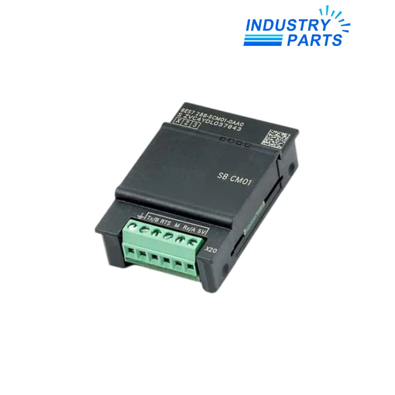
Siemens 6ES7288-5DT04-0AA0 SB DT04 Digital I/O Signal Board
A compact S7-200 SMART signal board adding two 24 V DC inputs and two 0.5 A transistor outputs.
Technical Summary
Siemens 6ES7288-5DT04-0AA0 is the SIMATIC S7-200 SMART SB DT04 signal board. It adds two 24 V DC digital inputs and two 24 V DC transistor outputs rated at 0.5 A per point.
The board connects through terminal X19: DQ f.0, DQ f.1, DI f.0, DI f.1, L+ and M. The input circuits are sinking IEC Type 1 channels with selectable per-channel filtering.
Its signal-board format extends a compatible CPU without consuming the footprint of a separate expansion module. CPU support, project configuration, load suppression and field supply must still be checked together.
Specifications
Features
Compact mixed I/O
Two inputs and two outputs are added in the CPU signal-board position.
Selectable input filtering
Each digital input can use the documented project filter settings.
Direct terminal identity
X19 terminal assignments keep the two inputs, two outputs and 24 V supply references explicit.
Transistor output control
The output pair is intended for documented 24 V DC loads within the published point rating.
About IndustryParts
https://www.industryparts.com/Exact-model handling for 6ES7288-5DT04-0AA0
IndustryParts keeps the complete 6ES7288-5DT04-0AA0 identity, requested quantity and installed-system evidence together so the proposed supply can be checked against the actual application before dispatch.

Compatibility
Host CPU
Confirm that the exact S7-200 SMART CPU supports the SB DT04 signal-board option.
Field circuits
Verify 24 V DC polarity, output load current, inrush and suppression for both connected devices.
Project record
Retain signal-board selection, addresses, input filters and output logic in the STEP 7-Micro/WIN SMART project.
Replacement
Document
Capture the CPU article number, SB DT04 label, X19 terminal map and project backup.
Isolate
Remove controller and field power under the approved lockout procedure before handling the board.
Test
Prove both inputs and both outputs individually, including safe-state and interlock behavior.
FAQ
What I/O does 6ES7288-5DT04-0AA0 add?
It adds two 24 V DC digital inputs and two 24 V DC transistor outputs rated at 0.5 A per point.
Which terminal information should accompany 6ES7288-5DT04-0AA0?
Provide the X19 wiring for DQ f.0, DQ f.1, DI f.0, DI f.1, L+ and M, plus photographs of conductor labels.
Can an expansion module replace 6ES7288-5DT04-0AA0 directly?
Not as a drop-in change. Hardware placement, addressing, project configuration and wiring all differ and require engineering review.
What output-load checks matter for 6ES7288-5DT04-0AA0?
Confirm steady current, inrush, switching frequency, inductive suppression, field supply and safe-state behavior for each 0.5 A point.
How should 6ES7288-5DT04-0AA0 be accepted after replacement?
Verify project recognition, both input states, both commanded outputs, diagnostics and every affected machine interlock.


