

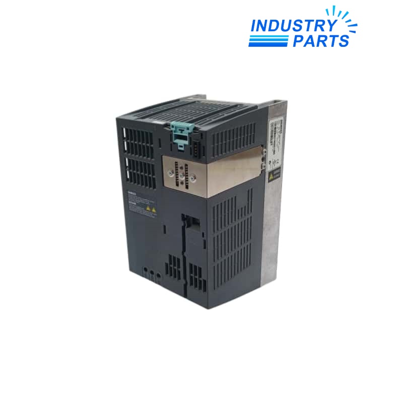
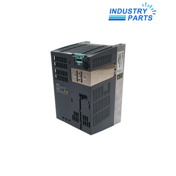
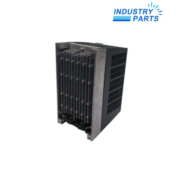
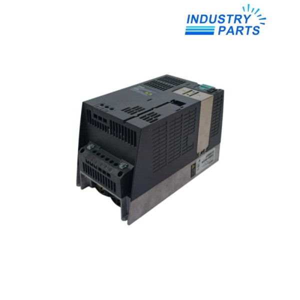
Siemens 6SL3252-0BB00-0AA0 SINAMICS Brake Relay
01Product Identification
Siemens 6SL3252-0BB00-0AA0 is a standard SINAMICS Brake Relay for a compatible Power Module. It allows the drive Control Unit to command an electromechanical motor holding brake through the Power Module. The relay includes the cable harness for connection to the Power Module and provides a normally open switching contact for the brake circuit.
02Engineering Data
| Manufacturer | Siemens |
|---|---|
| Article Number | 6SL3252-0BB00-0AA0 |
| Product Type | SINAMICS Brake Relay for Power Module |
| Control Connection | Via the Power Module |
| Output Contact | Normally open contact |
| Switching Capability | 250 V AC / 16 A or 30 V DC / 12 A, general-purpose contact rating |
| Maximum Conductor Cross-Section | 2.5 mm2 |
| Degree of Protection | IP20 |
| Included Accessory | Cable harness for connection to the Power Module |
| Product Lifecycle | Active product in the current Siemens listing |
| Safety Classification | Standard Brake Relay; not the Safe Brake Relay variant |
03Functions
Operational Functions
- Provides a normally open switching contact to control a motor-brake solenoid.
- Connects to the compatible Power Module through the included cable harness.
- Allows the Control Unit motor-brake function to operate the external brake circuit.
- Supports AC or DC brake circuits within the documented contact rating and wiring requirements.
- Compact IP20 construction installs near the Power Module power terminals on the shield connection plate.
- The standard Brake Relay must not be confused with the separate Safe Brake Relay article.
Product Identity
- Manufacturer: Siemens
- Model: 6SL3252-0BB00-0AA0
- Product Type: SINAMICS Brake Relay for Power Module
04System Integration
- Use only with Power Modules and Control Units for which Siemens approves this Brake Relay.
- Match brake-coil voltage, current, rectifier, external supply, surge suppression, conductor size and protective devices.
- Follow the current circuit diagram for AC or DC brake-coil wiring and protective-earth requirements.
- Configure the motor holding-brake function and timing in the drive parameter set.
- Do not use this standard relay as a safety-rated brake-control component; select the approved Safe Brake Relay when the safety function requires it.
05Applications
Typical Uses
- Motor holding-brake control in compatible SINAMICS drive systems.
- Vertical or suspended loads where the drive controls a mechanical holding brake, subject to the machine safety design.
- Machine axes requiring drive-coordinated brake release and engagement.
- Replacement of the same standard Brake Relay article in an approved Power Module installation.
Selection Boundary
- Match the exact standard Brake Relay article number.
- Verify Power Module approval and brake-coil electrical data.
- Use the Safe Brake Relay variant when required by the validated safety concept.
06Lifecycle
- The current Siemens product record lists 6SL3252-0BB00-0AA0 as an active product.
- Record the connected Power Module, Control Unit, brake-coil data, rectifier, external supply and drive parameters before replacement.
- Inspect the cable harness, relay contact, terminals, surge suppressor and protective earth.
- A Safe Brake Relay has different function and wiring and is not identified by this article number.
- After installation, verify brake release and engagement timing, contact switching, coil voltage, stopping behavior, alarms and repeated operating cycles.
FAQFrequently Asked Questions
What is Siemens 6SL3252-0BB00-0AA0?
It is a standard SINAMICS Brake Relay that connects a compatible Power Module to an electromechanical motor holding brake.
What contact does the relay provide?
It provides a normally open contact with the documented general-purpose switching capability for the brake circuit.
Is the Power Module cable included?
Yes. Siemens lists the cable harness for connection to the Power Module as included.
Is this the Safe Brake Relay?
No. This article is the standard Brake Relay. The Safe Brake Relay is a different product and must be selected when the validated safety concept requires it.
What must be checked before wiring the brake?
Confirm coil voltage and current, rectifier, external supply, surge suppression, conductor size, protective earth and the current Siemens connection diagram.
What should be tested after replacement?
Verify brake release and engagement timing, coil voltage, relay switching, stopping behavior, drive parameters, alarms and repeated operating cycles.
+Recommended Models
| 077092 | XC-1500-580-WT-RD | AVAYA J139 700513916 |
| 2CDG 110 063 R0011 | M200,52121556 | 94.74SMA |
| SMC5500/S SMC5500050407 | MR-52 10278 | REV.1.2.021 |
| VFF5 | IO-SDC1 | EZE-AC750T |
| K-EW215L03E | STI-3150 | SQ121B6220 |
| EV45 5363 | GLB161.1E | A20 48250080 |
| ATI3D-00 | CP-168EL-A | SPD910-300Pa |
| RLU232 | CS94202 | EXD5314CE |
| E244-16C-G-LW-DS-CR-SQ-BR | BMXXBE1000H | MMC-120A-F000 |
| 000518-003 NH30-200 PPM TXL-NH3 | EW300 | 342911 |


