

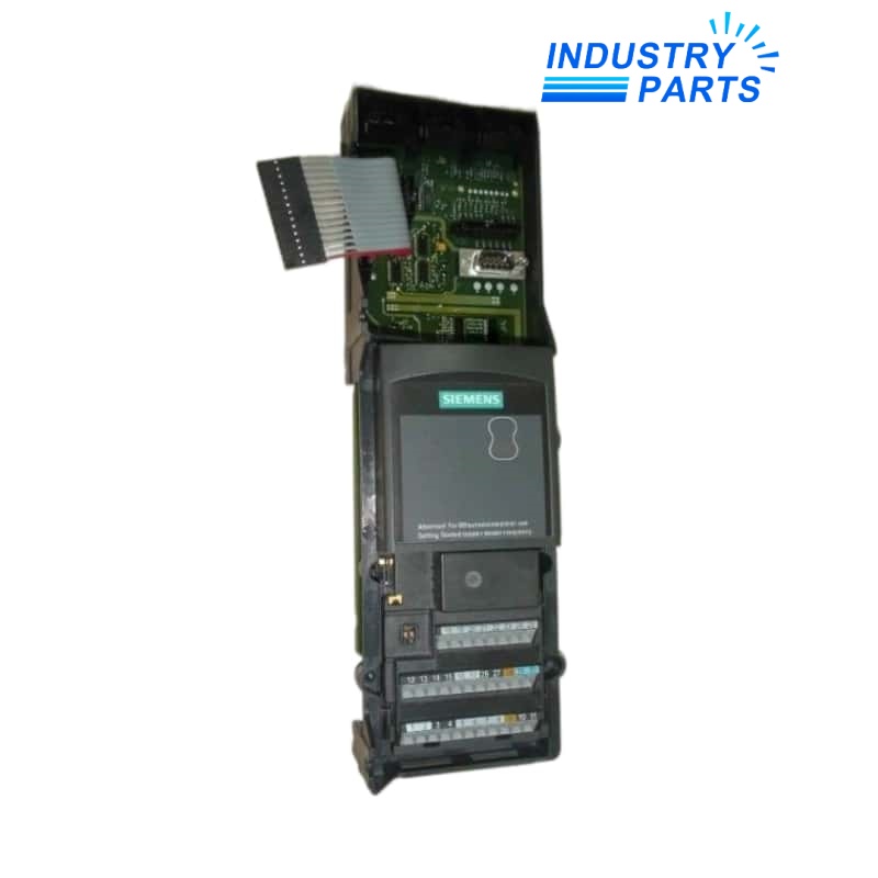
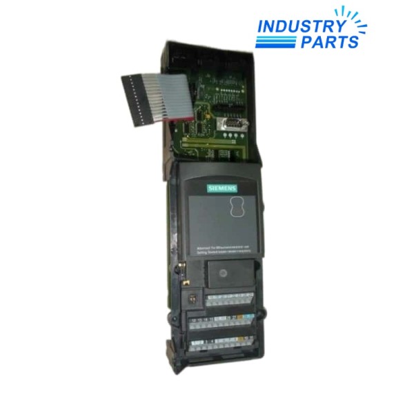
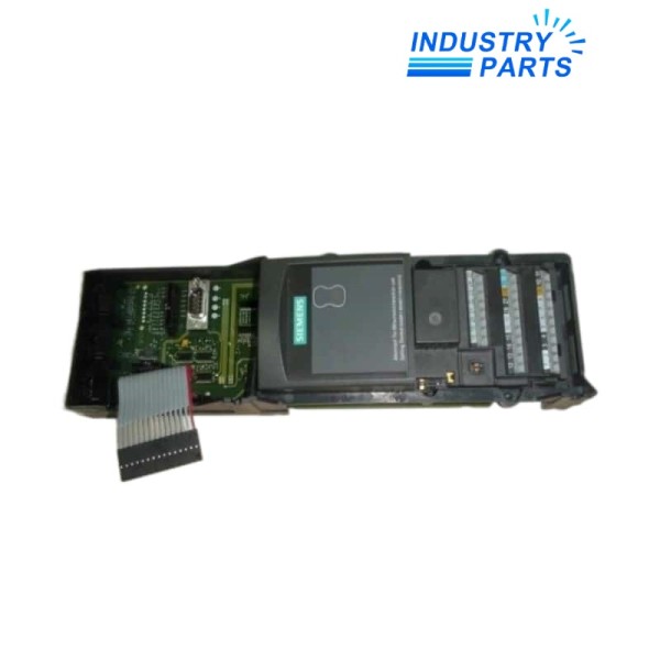
Siemens 6SL3351-6GE33-1AA1 MICROMASTER Control Interface Board
A replacement control interface board for the 380–480 V, 310 A MICROMASTER 440 GX drive execution.
Overview
6SL3351-6GE33-1AA1 is the Siemens replacement Control Interface Board assigned to the MICROMASTER 440 GX power section in the 310 A drive class. Siemens spare-parts documentation lists the board for 3 AC 380–480 V, 50/60 Hz service.
The complete 6SL3351-6GE33-1AA1 MLFB must be compared with the drive nameplate and installed board. Similar 6SL3351 references cover different current classes and power-section executions and are not interchangeable by appearance.
Specs
| Manufacturer | Siemens |
|---|---|
| Model | 6SL3351-6GE33-1AA1 |
| Drive Family | MICROMASTER 440 |
| Power-Section Frame | GX |
| Product Type | Replacement Control Interface Board |
| Supply Class | 3 AC 380–480 V |
| Supply Frequency | 50/60 Hz |
| Assigned Drive Current Class | 310 A |
| Service Position | Internal power-stage control interface |
| Ordering Boundary | Complete GE33-1AA1 code required |
| Host Evidence | Drive MLFB, serial number, board label and cabinet position |
| Configuration Evidence | Parameter set, option modules and communication arrangement |
| Handling | Drive isolation, discharge verification and ESD control |
| Commissioning | Diagnostics, parameter comparison and controlled motor test |
Features
Manufacturer-assigned replacement board for the 310 A MM440 GX execution.
Complete 1AA1 suffix retains the documented service revision.
Separates the 310 A board from 210 A, 260 A, 380 A and 490 A alternatives.
Maintains the interface between drive control electronics and the matched power section.
Applications
- Service replacement in a documented 310 A MICROMASTER 440 GX drive.
- Legacy conveyor, fan, pump or process-drive cabinets retaining the original MM440 architecture.
- Repair programs that preserve drive parameters, option boards and cabinet wiring.
Lifecycle
- Back up the MICROMASTER parameter set and capture the complete drive and board labels.
- Photograph every control and power-stage plug before removal and note adjacent option hardware.
- Observe the cabinet isolation, stored-energy and ESD procedure before handling 6SL3351-6GE33-1AA1.
- After exchange, compare parameters and diagnostics, then verify direction, interlocks, communications and current under a controlled load.
FAQ
Can a visually identical 6SL3351 board replace 6SL3351-6GE33-1AA1?
Not on appearance alone. The current class, frame, complete suffix, connector arrangement and documented Siemens service relationship must all agree.
What evidence is most useful when quoting 6SL3351-6GE33-1AA1?
Provide the drive nameplate, board labels, cabinet position, plug photographs, parameter backup and the diagnosed fault history.
Why should the original parameter set be saved before changing 6SL3351-6GE33-1AA1?
The board belongs to a commissioned drive; motor data, control mode, limits, I/O and communications must be restored to the approved baseline.
How is an installation issue distinguished from a faulty 6SL3351-6GE33-1AA1?
Recheck plug seating, grounding, option boards, drive supply and diagnostics before condemning the board, then use the approved static and controlled-run tests.
What proves a successful 6SL3351-6GE33-1AA1 exchange?
Stable diagnostics, matching parameters, correct interlocks and communications, correct motor direction and acceptable current during the controlled-load test.
Recommended Models
| 2961TC | D5096S | OW 300-09-CAN |
| 6FX8002-5DA11-1AE5 | JL087A JL087-61002 X372 | AEG/EMG EVK 800.04R |
| Fibro KTD 8507.02 F-RZ/400/XF/WK/WTX/S52/SA/3/4/S/00/K | 1794-OF4I | BRRTGR31 |
| NDD-0300 | ABE7 R16S210 | T/PI/S/-40 |
| LT410 | Safety-MS2 | MR-4 |
| DRN80MK4/BE1/MM07MO/TH | 6ES7658-1GX08-2YT7 | 571302.9001.01 |
| MPR200 496600 299552 | SP-420 | Schneider 140CRP93100 |
| ABB TU840 / 3BSE020846R1 | LS 703 336976-36 | 6ES5281-4UP12 |
| 7-119-WASI-SS02-M12-8-V2 | 604T2 | GMN HSX 150-18000/16 R306178 |
| ED806US0M140 | AD8851.19 0022698 | Hach Lange 6860103 6860303 |


