

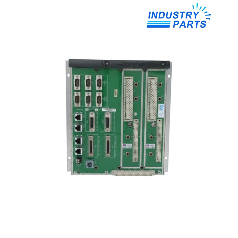

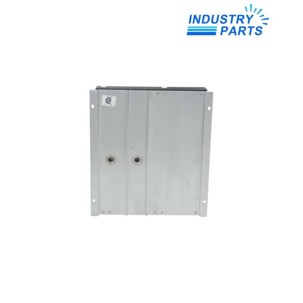
Triconex 7400150-270 Field Termination Panel Assembly
A legacy Tricon field-termination assembly that must be sourced from its exact label, keyed interface and controlled cabinet drawing.
Product Overview
7400150-270 is a legacy Triconex assembly identity associated with field termination hardware in the Tricon safety-system architecture. Termination panels connect field conductors to the assigned I/O module through an engineered and keyed cable path.
The -270 assembly must remain tied to its controlled panel drawing, keyed connector, component population and compatible I/O module. Voltage, point count and component values must be taken from that exact installed design.
Performance
- Maintains a traceable field-termination boundary for the installed Tricon system.
- Supports controlled routing between field conductors and the assigned controller I/O cable.
- Allows terminal, connector and component condition to be verified during safety maintenance.
- Preserves keyed-interface control intended to prevent an incompatible connection.
- Supports revision-led receiving inspection for a legacy spare.
Technical Details
| Manufacturer | Schneider Electric / Triconex |
|---|---|
| Model | 7400150-270 |
| Product Family | Tricon safety system |
| Product Type | Field termination panel assembly |
| Primary Role | Field wiring termination and routing |
| I/O Module Pairing | Confirm from installed rack, slot and controlled Tricon documentation |
| Interface Cable | Match exact part number and keyed connector |
| Terminal Schedule | Use the current site drawing and red-line record |
| Component Population | Verify fuses, resistors, jumpers and links from the physical panel |
| Mounting Context | Approved Tricon termination enclosure or panel |
| Replacement Rule | No alternate without drawing, connector, cable and I/O compatibility review |
| Receiving Control | Compare full model, revision, connector, terminal pattern and condition |
| Electrical Ratings | Confirm from the exact panel drawing and compatible I/O module |
System Integration
- Capture the 7400150-270 label, terminals, connector, component population and cabinet location in clear photographs.
- Identify the connected Tricon I/O module, rack and slot, interface cable and safety-function tag list.
- Apply the approved bypass and energy-isolation procedure before field conductors are moved.
- Reconcile every jumper and red-line change with the current controlled drawing.
- Complete continuity, point simulation, diagnostics, functional response and bypass-restoration checks.
Applications
- Legacy Tricon field termination in a safety instrumented system.
- Like-for-like panel exchange based on exact assembly evidence.
- Cabinet refurbishment where terminal and cable traceability must be retained.
- Proof-test access for field signal paths under the site safety procedure.
FAQ
What is the minimum quotation package for 7400150-270?
Provide all labels, front and rear photographs, terminal and component layout, interface cable, connected I/O module, cabinet drawing and safety-function channel list.
Why does 7400150-270 require a complete installed-system record?
Its assembly wiring, connector keying, component population and I/O pairing are revision controlled, so the panel cannot be selected from the part number or appearance alone.
Can connector fit alone prove a 7400150-270 replacement is correct?
No. Connector keying, cable routing, compatible I/O module, terminal assignments, component values and the safety application must all agree.
How should field modifications on 7400150-270 be managed?
Photograph and red-line every jumper, link, fuse, resistor, shield and external power change before removal, then validate the intended as-built state.
When should a 7400150-270 substitution be escalated to engineering?
Escalate whenever the exact label, drawing, cable, I/O-module pairing or safety validation cannot be confirmed before purchase.
Recommended Models
| 67CFR-239 250PSI/0-125PSI | SENSORPROBE4,SP4 | F-RZ/400/XF/WK/WTX/S52/SA/3/4/S/00/K |
| SS1544CB14 | EMG 12-RC/10UF/100K | MTL4046C |
| DUS360CR | 471 007302910 | Z 11154A |
| BCS0038 BCS M12T4D2-POM40C-S04G | 205 10D 1 1 4123050/60 | 00241091 5404 B 12.0 EF G1/2 |
| N3R352C-08E4 | TSXDSY08R5 | Siemens ISKAMATIC B EU15-3 |
| A1NE251 034058 | F72G-3GN-AE3 | ROD 426 B 1800 |
| CNX-B12B | 7DM435.7 | TT180N16KOF G22M4 |
| DRL132S4BE11/TF/ES7S | WDP3-314.9817 | PS-24V-1.5A |
| BK70G20-54VL/DPE08XB4-TB-S/ESX010A9 | ACC-IRS-4700 | CP-132UL-I/DB9M |
| ATV12H075M2 | 6AU1400-2PA23-0AA0-Z | CBL-HD-6 |


