

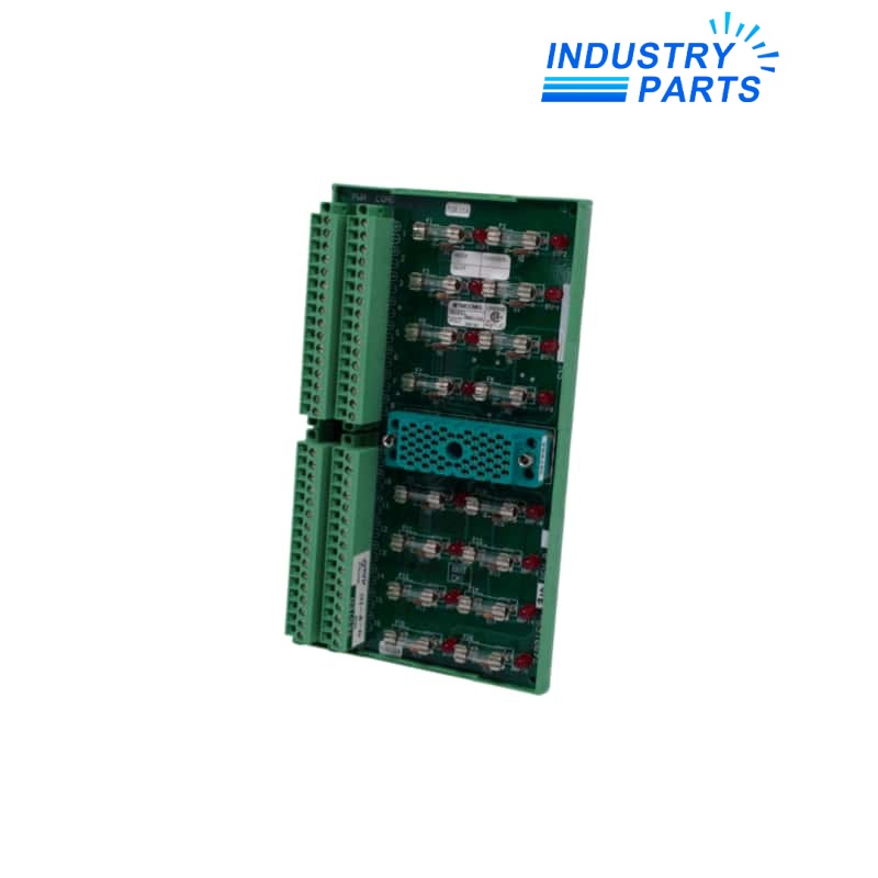

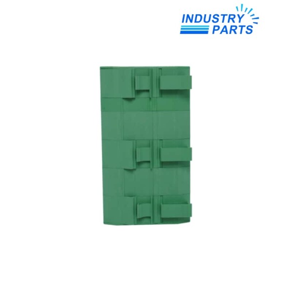
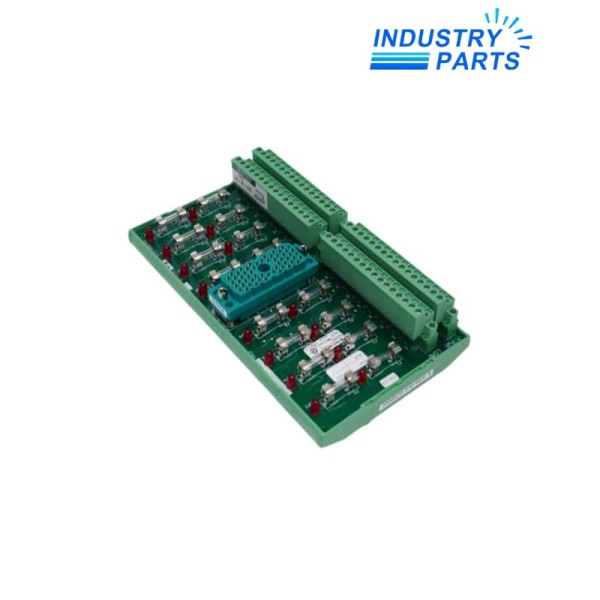
Triconex 7400166-380 External Termination Panel Assembly
A revision-controlled Tricon field-termination assembly whose panel identity, interface cable and I/O-module pairing must be matched together.
Key Information
7400166-380 is an assembly identity associated with a Tricon external termination panel. In the Tricon architecture, termination panels form the controlled interface between field conductors and the keyed controller I/O cable path.
The complete part number must be matched with the installed panel drawing, connector keying, field schedule and compatible Tricon I/O module so electrical and channel requirements remain tied to the validated safety-system design.
Functions
- Provides an organized field-termination point for the engineered Tricon I/O path.
- Maintains the keyed connection boundary between termination hardware and the controller cable.
- Supports cabinet separation between field wiring and controller chassis hardware.
- Keeps terminal, fuse and channel requirements tied to the controlled panel drawing.
- Preserves an exact assembly identity for legacy-system maintenance and receiving control.
Specifications
| Manufacturer | Schneider Electric / Triconex |
|---|---|
| Model | 7400166-380 |
| Product Family | Tricon safety system |
| Product Type | External termination panel assembly |
| Primary Role | Field wiring termination and routing to the assigned Tricon I/O path |
| Interface Control | Match keyed connector and approved Tricon interface cable |
| I/O Compatibility | Confirm from the installed module, cabinet drawing and field-termination guide |
| Panel Drawing | Use the site-controlled drawing for terminal and fuse assignments |
| Field Wiring | Preserve conductor, shield, common and power designations |
| Installation Context | Approved Tricon system and termination enclosure |
| Replacement Rule | No alternate without part-number, drawing, cable and I/O-module review |
| Receiving Control | Compare full label, assembly revision, connectors, terminals, fuses and condition |
| Documentation Boundary | Electrical ratings remain governed by the exact system drawing and compatible I/O module |
Installation
- Photograph the complete 7400166-380 label, every terminal, fuse, jumper, connector and cable tag before disturbance.
- Record the connected Tricon I/O module, rack, slot, interface-cable number and field drawing revision.
- De-energize or place the safety function in the approved bypass and maintenance state before field work.
- Transfer wiring only from a checked terminal schedule and verify connector keying before mating.
- Perform continuity, insulation, channel simulation, diagnostic and safety-function tests under the site procedure.
Lifecycle
- Keep the 7400166-380 panel drawing, cable identity and compatible I/O module in one asset record.
- Inspect terminals, fuses, connectors, wiring markers and enclosure condition during planned proof testing.
- Record every jumper or field modification so replacement does not restore an obsolete drawing state.
- Treat lifecycle replacement as a safety-system change requiring impact analysis and validation.
FAQ
What evidence is required to quote 7400166-380 responsibly?
Provide the full 7400166-380 label, front and rear photographs, terminal and fuse layout, keyed connector, interface cable, compatible I/O module and cabinet drawing.
Can 7400166-380 be selected from a similar-looking Tricon panel?
No. Tricon termination connectors are keyed by function and voltage; the exact assembly, cable and I/O-module pairing must be verified.
Which field changes must be captured before replacing 7400166-380?
Document jumpers, fuse values, wire links, spare terminals, shields, commons, external power and every deviation from the original drawing.
How should 7400166-380 be tested after installation?
Use the approved safety-maintenance plan for continuity, insulation, point simulation, diagnostics, trip or permissive response and restoration of all bypasses.
When should a 7400166-380 substitution be rejected?
Reject it when the connector keying, drawing, I/O-module compatibility, terminal arrangement, revision or safety validation cannot be demonstrated.


