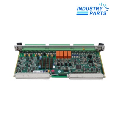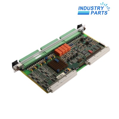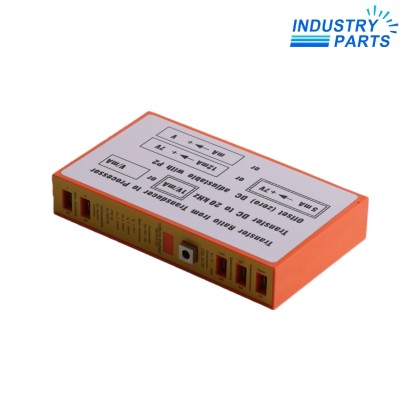

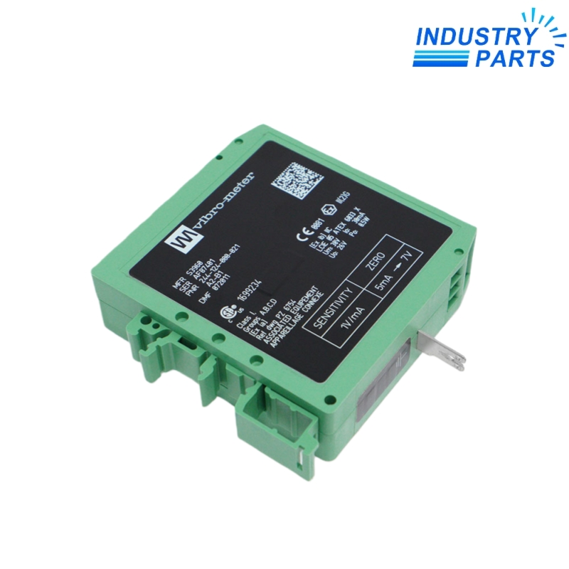


Vibro-Meter GSI124 244-124-000-022 Galvanic Separation Unit
Warranty: 1 year
Condition : brand new in factory sealed box
Email: sales@mvme.cn
Chat online: +86 18030175807
Detail
- Product NameVibro-Meter GSI124 244-124-000-022 Galvanic Separation Unit
- Item NO.GSI124 244-124-000-022
- Weight0.1300 kg = 0.2866 lb = 4.5856 oz
- CategoryTSI
- BrandVibro-Meter
- Creation Time2025-11-26
- Vibro-Meter GSI124 244-124-000-022 galvanic separation unit for compatible two-wire CE, IPC and IQS4xx measurement chains. Manufacturer-rated 4 kVRMS isolation, DIN-rail mounting, 0 to 70°C operation and 130 g weight. The manufacturer identifies GSI124 as obsolete and names GSI127 as its successor; wiring orientation, grounding, cable length and ordering options must be checked before replacement.
GSI124 244-124-000-022 Galvanic Separation Unit
A DIN-rail galvanic separation unit for compatible two-wire Vibro-Meter transducers and signal conditioners. It powers the field-side device, transfers the dynamic signal to the monitoring side and separates the measurement chain by 4 kVRMS.
Product information
The GSI124 belongs to the Vibro-Meter product line. Manufacturer documentation describes it as a versatile galvanic separation unit for piezoelectric transducers with integrated electronics (CE series), piezoelectric-transducer signal conditioners (IPC series) and proximity-probe signal conditioners (IQS4xx series).
It is intended for high-frequency two-wire transmission systems and can supply compatible electronic systems consuming less than 20 mA. The unit supports long-distance AC-signal transmission, rejects frame/ground-noise voltage and avoids AC pickup between the sensor case and sensor poles. The manufacturer also published an Ex ordering option for use with certified measurement chains in potentially explosive atmospheres.
Technical data
| Manufacturer / product line | Vibro-Meter (Meggitt SA) |
|---|---|
| Type | GSI124 galvanic separation unit |
| Part number supplied | 244-124-000-022 |
| Compatible device groups | CE-series transducers, IPC-series signal conditioners, IQS4xx-series signal conditioners |
| User-side supply | 20 to 30 VDC with IPC/CE; 22.5 to 30 VDC with IQS4xx |
| Current consumption at 24 VDC | ≤20 mA no-load; ≤50 mA at 12 mA field current; ≤70 mA at 20 mA or field-side short circuit |
| Field-side two-wire supply | 21.5 VDC ±2.5 VDC, no load |
| Field current / short-circuit limit | 0 to 20 mA / ≤30 mA |
| Monitor-side output | Voltage output; dynamic range ≥2 VDC to ≤supply −2.5 VDC with 10 kΩ load; output impedance ≤1 Ω |
| Transfer sensitivity | IPC/CE: 1 V/mA ±10 mV/mA; IQS4xx: 3.2 V/mA ±32 mV/mA — ordering option dependent |
| Bandwidth | IPC/CE options B1/B2: DC to 20 kHz within ±0.5 dB; IQS4xx option B3: DC to 10 kHz within ±0.5 dB |
| Linearity / galvanic separation | <0.2% / 4 kVRMS |
| Operating / storage temperature | 0 to 70°C / −20 to +85°C |
| Humidity | Operating up to 90% RH; storage up to 95% RH; non-condensing |
| Housing / connection / mounting | Green PA 6.6 polyamide housing; screw terminals; DIN-rail mounting |
| Weight | 130 g |
Data scope: values are limited to manufacturer-published GSI124 data. Exact approval, sensitivity and zero-offset ratings depend on the complete ordering suffix shown on the unit nameplate.
Applications and selection
- Two-wire vibration and proximity measurement chains using compatible CE, IPC or IQS4xx devices.
- Long cable runs where current-to-voltage transfer and strong rejection of frame voltage are required.
- Panel or cabinet installations associated with machinery monitoring and protection systems.
- Certified hazardous-area measurement chains only when the complete GSI124 Ex ordering option and loop approvals are confirmed.
GSI124 vs GSI127: key differences
The manufacturer names GSI127 as the successor to GSI124, but the two units are not automatically interchangeable without checking the complete measurement chain. The comparison below is limited to manufacturer-published information.
| Comparison point | GSI124 / 244-124-000-022 | GSI127 successor |
|---|---|---|
| Lifecycle | Legacy unit; manufacturer documentation identifies it as no longer available. | Manufacturer-named replacement; newer base PNR 244-127-000-021. |
| Supported signal types | Primarily two-wire current-transmission chains using CE, IPC and IQS4xx devices. | Supports current- or voltage-output chains; also compatible with industry-standard IEPE and 4 to 20 mA loop-powered sensors/transmitters, subject to ordering option. |
| Sensor-side input range | 0 to 20 mA on the two-wire transmission line. | 0 to 20.75 mA or 0 to 20.3 VDC. |
| Transfer functions | 1 V/mA for IPC/CE or 3.2 V/mA for IQS4xx, with option-specific zero offset. | 0.5, 1 or 3.2 V/mA, plus 1 V/V or −1 V/V; configurable zero-offset variants. |
| Galvanic separation | 4 kVRMS between sensor and monitor sides. | 4 kVRMS between sensor and monitor sides, plus 50 VRMS between the power supply and output signal for a floating output. |
| Operating temperature | 0 to 70°C. | −20 to 70°C. |
| Diagnostics / functional safety | Legacy data sheet publishes standard and Ex variants; no comparable remote chain-health diagnostics are specified. | Includes automatic remote measurement-chain health/status diagnostics and is suitable for SIL 2 functional-safety contexts. |
| Terminals | Screw-terminal connections; monitor side at the top and sensor side at the bottom. | Removable screw-terminal connectors; sensor side at the top and monitor side at the bottom. |
| Ground connection | Uses a black flying grounding lead connected from the underside of the unit to the DIN rail. | The GSI124 grounding lead is removed; the manufacturer states that it is not required by GSI127. |
| Replacement impact | Existing field and monitor cables terminate in the legacy orientation. | Cable routing or cable length may require adjustment because the sensor- and monitor-side positions are reversed. |
Lifecycle and replacement guidance
For related monitoring components, browse the TSI category or the Vibro-Meter product collection.
Frequently asked questions
What does the GSI124 do?
It powers compatible two-wire transducers or signal conditioners, transfers their dynamic signal to the monitoring side and provides 4 kVRMS galvanic separation with high rejection of frame voltage.
Is 244-124-000-022 the complete configuration code?
The manufacturer ordering scheme also uses environment and transfer-function suffixes. Confirm the complete nameplate before ordering, especially for Ex approval and sensitivity/zero-offset matching.
Has the GSI124 been discontinued?
Yes. Manufacturer documentation issued in October 2018 identifies the GSI124 as no longer available. No separate exact factory EOL date is stated in the reviewed manufacturer documentation.
What is the manufacturer-named replacement?
The manufacturer names the GSI127 as the replacement. The correct GSI127 ordering options must be selected for the original sensor or signal-conditioner chain.
Can GSI127 replace GSI124 without wiring changes?
Not always. The manufacturer documents reversed top/bottom sensor- and monitor-side connection positions, possible cable-length adjustment and removal of the GSI124 grounding lead. Verify wiring, transfer function and hazardous-area approval before commissioning.
You May Also Like
-
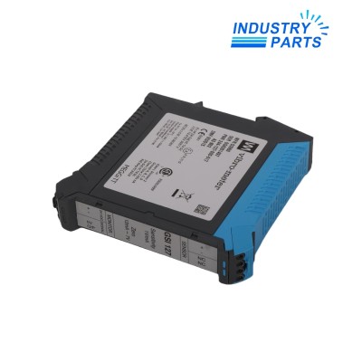 Vibro-Meter GSI127 244-127-000-017 A1-B02 Galvanic Separation Unit
Vibro-Meter Galvanic Separation Unit