

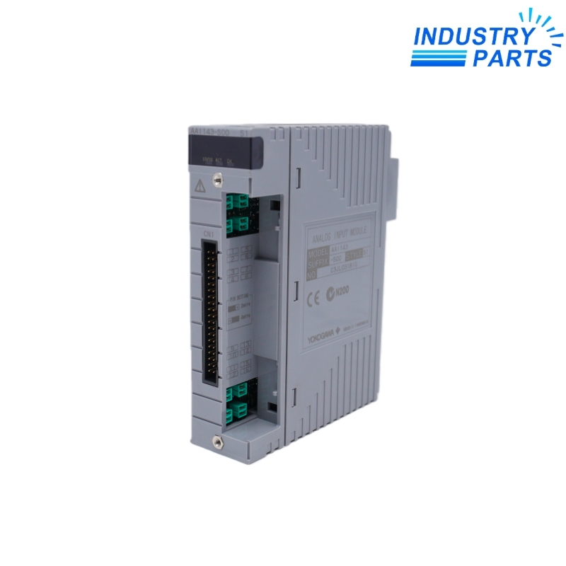


Yokogawa AAI143-S00 16-Channel Analog Input Module
A 16-channel isolated 4–20 mA analog input module for Yokogawa field-control-unit I/O assemblies.
Key Information
AAI143-S00 is the S00 execution of Yokogawa's AAI143 analog input module. The AAI143 family provides sixteen isolated 4–20 mA input channels for process transmitters in CENTUM field-control-unit applications.
The complete S00 suffix, terminal or interface adapter, field wiring and project channel definition must remain part of the replacement record. The S standard-type execution should not be confused with the separately designated HART variant.
Functions
- Acquires sixteen isolated 4–20 mA process-input channels.
- Separates channel signal paths for robust field-loop integration.
- Interfaces with the documented Yokogawa pressure-clamp terminals or KS-cable adapter arrangement.
- Provides module-level identification and diagnostics within the field control unit.
- Supports revision-controlled replacement of installed process-input hardware.
Specifications
| Manufacturer | Yokogawa |
|---|---|
| Model | AAI143-S00 |
| Base Model | AAI143 |
| Product Type | Analog input module |
| Input Signal | 4–20 mA |
| Input Channels | 16 |
| Isolation | Isolated channels |
| Execution | S standard-type family; complete S00 suffix retained |
| Pressure-Clamp Terminal Options | ATA4S or ATA4D |
| KS-Cable Interface Adapter | ATK4A |
| Compatible KS Cable | KS1 |
| Terminal Board Path | AEA4D under the documented arrangement |
| Configuration Control | Match suffix, node, slot, terminal hardware and project channel map |
Installation
- Export the channel ranges, scaling, alarm handling and tag references before removing AAI143-S00.
- Photograph the S00 label, node, slot, terminal hardware, commons, shields and loop-power arrangement.
- Confirm whether ATA4S, ATA4D or the ATK4A/KS1 interface path is installed.
- Transfer conductors only from a checked loop schedule and verify polarity before energization.
- Inject traceable current on every used channel and verify raw value, engineering units, alarms and controller logic.
Lifecycle
- Keep the S00 suffix, terminal assembly and channel map with calibration records.
- Trend open-loop and range events so transmitter or wiring faults are not misclassified as module faults.
- Inspect terminal torque, loop power and shield practices during planned work.
- Treat an AAI143-H execution or another module as a separate compatibility decision.
FAQ
What evidence prevents an AAI143-S00 suffix mismatch?
Send the complete AAI143-S00 label, node and slot, terminal or KS-cable hardware, controller release and channel schedule.
Can AAI143-S00 be replaced by a HART-designated AAI143 execution?
Not automatically. Compare suffix, communication requirement, terminal path, system release and the validated project before approval.
How should an AAI143-S00 spare be tested?
Use traceable 4–20 mA injection on all required channels and verify scaled values, alarms, diagnostics and project references.
What should be checked when one AAI143-S00 channel is unstable?
Review loop power, field transmitter, terminal condition, grounding, shield routing and a known current-source result before changing the module.
Which accessories must be listed with AAI143-S00?
State whether the order includes or reuses ATA4S, ATA4D, ATK4A, KS1 cable, AEA4D terminal board or other site-specific hardware.


