

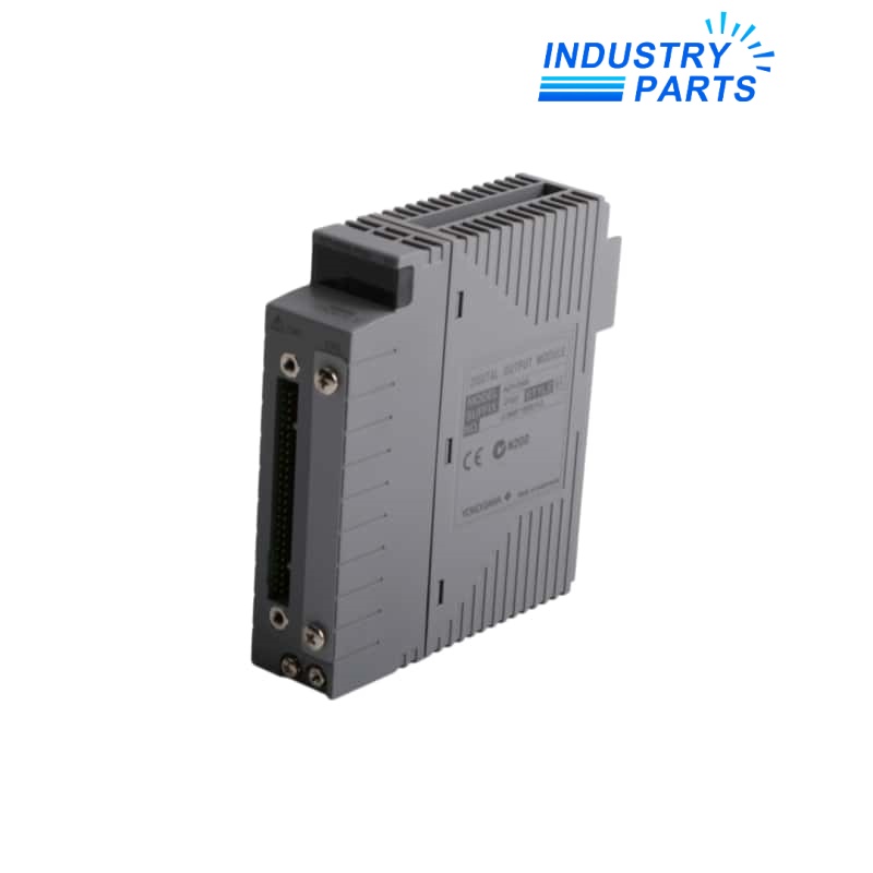


Provides 64 output points for an ST7-compatible migration arrangement.
Key Information
ADV569-P00 is a Yokogawa digital output module used when replacing a compatible ST7 output path in CENTUM VP. It provides 64 isolated outputs with a common minus side for every 16 channels.
The suffix P00 is specific: P selects pulse-width and time-proportional output functions, the first 0 is fixed, and the final 0 identifies the basic type rather than the ISA Standard G3 option.
Functions
Groups the common-minus side in four 16-channel groups.
Supports pulse-width output and time-proportional output functions selected by the P suffix.
Connects through the dedicated Yokogawa cable route used by the compatible-ST module family.
Specifications
| Manufacturer | Yokogawa Electric Corporation |
|---|---|
| Exact Model | ADV569-P00 |
| Control Platform | CENTUM VP FIO |
| Product Type | Digital output module for compatible ST7 |
| Output Channels | 64 |
| Isolation | Isolated module architecture |
| Common Arrangement | Common minus side every 16 channels |
| Function Suffix | -P: pulse-width function and time-proportional output function |
| Middle Suffix | 0: fixed value |
| Environmental Suffix | 0: basic type |
| ISA Standard G3 | Not selected; the G3 alternative is suffix 1 |
| Signal Connection | Dedicated Yokogawa cable |
| Pressure Clamp Terminal | Not supported for this module |
| MIL Connector Cable | Not supported for this module |
| Maximum 5 VDC Consumption | 800 mA |
| Installation Availability | Documented for supported CENTUM VP FCU and node-unit arrangements |
| Ordering Rule | Specify the complete model and suffix code |
Installation
- Export the original ST7 point map, pulse-width parameters, time-proportional cycle settings, fail-safe states and alarm behavior.
- Identify all four 16-channel common groups and confirm external power segregation before moving conductors.
- Match the dedicated cable and terminal-board route; do not substitute pressure-clamp or MIL connector hardware.
- Confirm the target CENTUM VP FCU or node-unit slot supports ADV569 and that the project database contains the correct compatible-ST definition.
- Commission each output group with loads made safe, then test commanded state, pulse timing, interlocks and bad-status handling.
Lifecycle
- Keep ADV569-P00 intact in drawings because P01 is the G3 variant.
- Archive the I/O database and as-built terminal references before ST-card migration.
- Review 5 VDC node-unit capacity with the 800 mA maximum module demand.
- Record point-by-point proof testing and the restored process permissives after commissioning.
About IndustryParts
https://www.industryparts.com/ST7 output migration is documented
IndustryParts matches ADV569-P00 to the 64-point ST7 wiring, dedicated cable and pulse-width configuration before release.
- P00 suffix retained
- Cable identity checked
- Output map preserved

FAQ
Why is the final zero important on ADV569-P00?
It identifies the basic environmental type; the closely related P01 code selects ISA Standard G3 and must not be treated as the same execution.
Can ADV569-P00 use a pressure-clamp terminal block?
No. Yokogawa documents the dedicated-cable connection for ADV569 and does not list pressure-clamp or MIL cable connection for this model.
What should be captured from the old ST7 installation before fitting ADV569-P00?
Save the 64-point map, common groups, power sources, pulse settings, fail-safe states, terminal references and interlock logic.
How should ADV569-P00 be load-tested without disrupting the process?
Use an approved outage or simulation plan, make field loads safe, test by 16-channel group and verify both command and feedback paths.
What can cause correct logic status but no field action from ADV569-P00?
A missing external output supply, common-minus error, cable or terminal-board mismatch, load fault or inhibited application path can leave the database state correct while the load remains inactive.


