

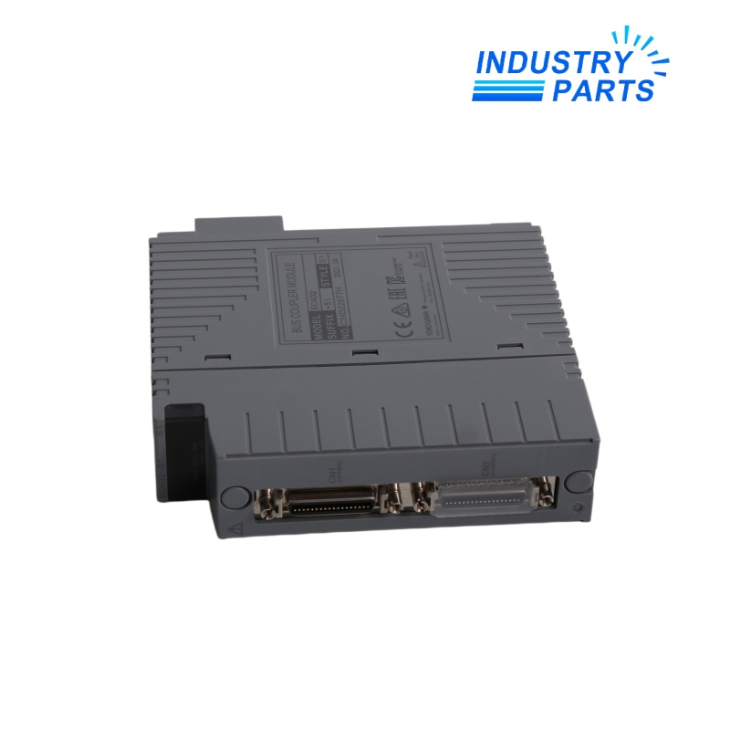


Yokogawa EC402-51 2-Port ESB Bus Coupler Module
An ESB bus master-interface module linking a Field Control Unit with N-IO or FIO node units.
Technical Summary
EC402-51 is a Yokogawa EC402 ESB Bus Coupler Module for N-IO and FIO systems. It installs in a supported Field Control Unit and connects the controller to node units through two front-panel ESB bus ports.
One EC402 can be used for a non-redundant bus, while two modules provide a dual-redundant ESB bus arrangement. The complete -51 identity should be maintained with the controller model and node topology.
Specifications
| Manufacturer | Yokogawa Electric Corporation |
|---|---|
| Model | EC402-51 |
| Product Family | CENTUM VP N-IO / FIO |
| Product Type | ESB Bus Coupler Module for N-IO/FIO |
| Interface Function | ESB bus master interface |
| Front Ports | Two ESB bus connector ports |
| Transmission Speed | 128 Mbps |
| Maximum Cable Length | 10 m upper, 10 m lower; 20 m total |
| Current Consumption | 0.5 A |
| Supported FCU Models | AFV30S/D, AFV40S/D, A2FV50S/D and A2FV70S/D |
| Redundancy | Two EC402 modules support dual-redundant ESB bus operation |
Features
- Provides the controller-side master interface for the high-speed ESB node bus.
- Carries upper and lower ESB connections through two accessible front connectors.
- Supports single-module and dual-redundant bus designs in compatible Field Control Units.
- Connects supported CENTUM VP controller hardware to N-IO and FIO node infrastructure.
Compatibility
- Confirm the Field Control Unit model and whether the ESB bus is single or dual redundant.
- For a non-redundant installation, follow the documented slot arrangement and fit the required dummy cover in the unused position.
- Verify upper and lower cable lengths, node count and ESB connector condition before release.
- Do not treat EC401, EC402 variants or another suffix as interchangeable without checking the complete Yokogawa system configuration.
Replacement
- Record controller slots, redundant partner status, node topology and upper/lower cable labels.
- Coordinate the maintenance window so the remaining communication path is not unintentionally interrupted.
- Use static-safe handling and inspect front connectors and backplane contacts before insertion.
- Confirm module recognition, redundancy state, node communication and system alarms after replacement.
FAQ
EC402-51: Which system details are needed for a quotation?
Provide the FCU model, CENTUM VP release, slot positions, redundancy arrangement, node count and photographs of both module labels.
Can one EC402-51 be replaced online in a redundant pair?
Only under the approved Yokogawa maintenance procedure and after confirming that the partner path is healthy and the system permits the exchange.
EC402-51: What cabling evidence reduces startup risk?
Record the upper and lower port assignment, cable length, destination node and connector condition before disconnection.
How should a refurbished EC402-51 be accepted?
Request traceability, port communication testing, backplane-interface checks and evidence of operation in a compatible controller arrangement.
EC402-51: What post-installation checks are essential?
Verify controller recognition, all expected nodes, redundancy status, diagnostic messages and communication stability under the normal scan load.
Recommended Models
| SIPOS 2SB5511-0CD10-4BC4-Z | 7MF1575-8AA | 6ES5420-4UA14 |
| 110S-MF2-31-0K1-2S | Lenze MCA 19S42-T20B0-Z0G0-KS5S00N-R0SU | S4-344410 |
| SCHNEIDER PM2200 | 1760-12bbb | J7MN-6R-26 |
| AZM 160-14YRPK | KFD2-CD-EX1.32 71763 | BL3.50/04/180 |
| FX2N-8ER-ES/UL | 1PH6163-4CF06-ZZ:K09 | PIC120.242C |
| 3000 / 1404-DM / A | 19000710 71 | P3-63/I4/SVB-SW/HI11 |
| Phoenix PPC 5315 SM 2900357 | 3IF772.9 | CE9A01 CE9GF01YE1 |
| F15 1RU | 1002UU01 852-920-001 | V6G05ZQ |
| Eaton DG1-34140FN-C21C | 32.1100.121-01.DVB | Mako U-130B |
| Allweiler SRZ111WWS12 32 | TM168B23S | 5SV8101-6KK |


