

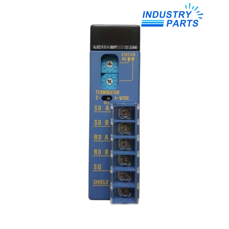
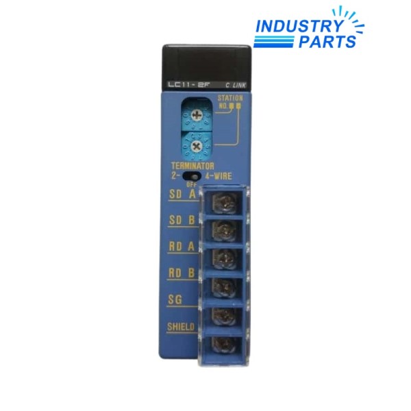
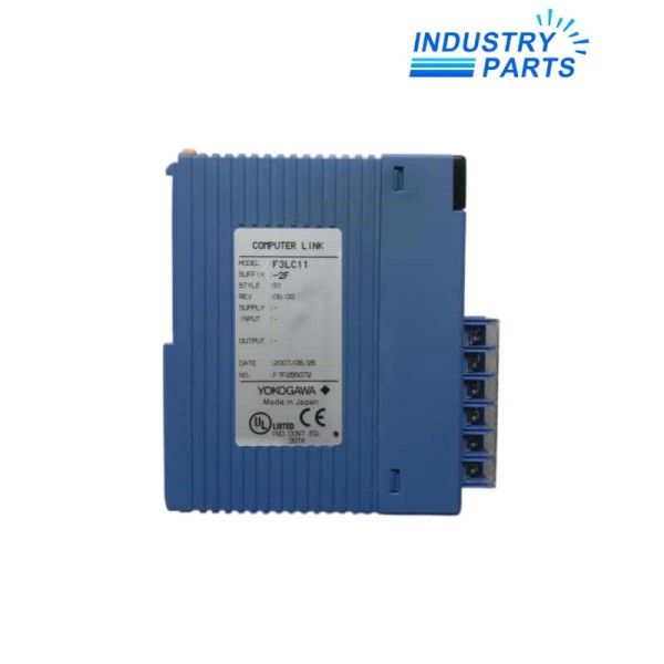
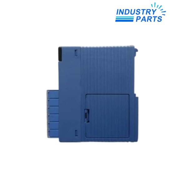
Yokogawa F3LC11-2F FA-M3 RS-422-A / RS-485 Personal Computer Link Module
A single-port FA-M3 communication module for personal-computer links over two-wire or four-wire RS-422-A / RS-485 networks.
Key Information
F3LC11-2F provides one RS-422-A / RS-485 personal-computer link port for the Yokogawa FA-M3 controller platform. It supports both two-wire and four-wire wiring arrangements.
The module includes a 220 Ω terminator that is selected according to whether the module is installed at the end of a two-wire or four-wire network. Yokogawa states that the module does not restrict the choice of FA-M3 CPU module.
Shield handling, signal-pair polarity and terminator position are part of the field installation. The exact cable system and every linked station should be recorded before an exchange.
Functions
Link supervisory computers
The serial port connects an FA-M3 system to a compatible personal computer or other supported serial station.
Support multidrop wiring
The module can participate in an RS-422-A / RS-485 arrangement with up to 32 linked modules.
Select the correct line termination
The built-in terminator supports end-of-line treatment for the selected two-wire or four-wire topology.
Maintain shield continuity
The SHIELD terminal connects internally to the FA-M3 power-supply FG path, making the documented grounding arrangement important.
Specifications
| Manufacturer | Yokogawa | Exact model | F3LC11-2F |
|---|---|---|---|
| Platform | FA-M3 | Module type | Personal computer link module |
| Interface | RS-422-A / RS-485 | Ports | 1 |
| Maximum transmission rate | 115 kbps | Wiring modes | Two-wire or four-wire |
| Maximum linked modules | 32 | Built-in terminator | 220 Ω |
| Dimensions | 28.9 × 100 × 83.2 mm | CPU restriction | No module-specific CPU restriction |
About IndustryParts
https://www.industryparts.com/Serial topology evidence prevents a mismatched spare
IndustryParts links the exact module with the network drawing, switch positions and requested quantity before a quotation is prepared.
- •Exact submitted model retained
- •Installed-system evidence reviewed
- •Requested quantity linked to the enquiry

Installation
Map the serial network
Record every station address, cable segment, converter and end-of-line module before shutdown.
Capture switch positions
Photograph the two-wire or four-wire selection and terminator setting on the installed module.
Preserve pair polarity
Label SDA/SDB and RDA/RDB conductors, or the combined pairs used by the two-wire arrangement.
Commission the link
Verify station communication, error-free traffic and the approved supervisory exchange after replacement.
Lifecycle
- Topology evidence
- Retain the complete multidrop drawing instead of documenting only the local slot.
- Termination control
- Only end-of-line modules should use the terminator setting required by the approved network.
- Communication record
- Store baud rate, station settings and converter details with the module label.
FAQ
What network drawing should accompany an F3LC11-2F enquiry?
Provide all linked stations, cable lengths, two-wire or four-wire topology, baud rate, converters and both end-termination points.
Can F3LC11-1F directly replace F3LC11-2F?
No. F3LC11-1F is the RS-232-C version, while F3LC11-2F provides an RS-422-A / RS-485 interface.
Why must the terminator switch be photographed on F3LC11-2F?
Its correct position depends on whether the module is at the network end and whether the field wiring uses two or four conductors.
Does F3LC11-2F require a particular FA-M3 CPU model?
Yokogawa states no module-specific CPU restriction, but the installed project, slot and serial configuration still need to be retained.
How should F3LC11-2F be accepted after service?
Confirm station addressing, stable serial traffic, correct termination and successful data exchange with every required peer.
Request a model-specific quotation
Send the complete F3LC11-2F label, requested quantity, delivery destination and installed-system context.


