


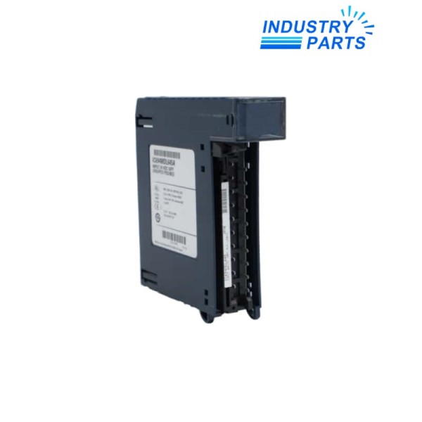
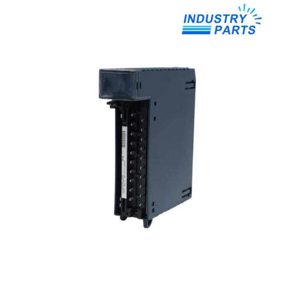
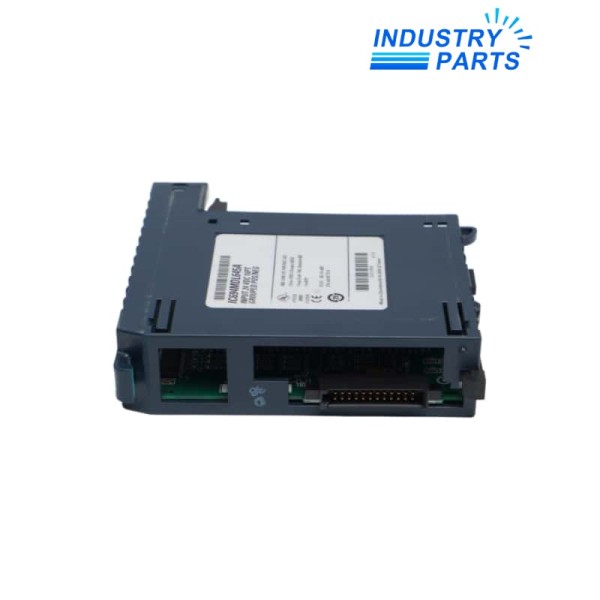
Emerson IC694MDL645LTC PACSystems RX3i 24 VDC Discrete Input Module
An LTC-revision RX3i input module for sixteen 24 VDC field states with positive- or negative-logic wiring.
Product Identification
IC694MDL645LTC is the LTC execution of the PACSystems RX3i IC694MDL645 input module. The base design accepts sixteen 24 VDC discrete inputs and supports positive- or negative-logic field wiring.
Its published input response is 7 ms on and 7 ms off. The module also draws 125 mA from the 24 VDC backplane supply, which belongs in the rack power budget.
The LTC suffix stays attached to the spare identity; the terminal map, field polarity and rack power calculation must all match before acceptance.
Engineering Data
- Input points
- 16
- Logic support
- Positive or negative logic
- Nominal field voltage
- 24 VDC
- Input range
- 20 to 30 VDC
- On-state threshold
- Above 11.5 V
- Input response
- 7 ms on / 7 ms off
- Backplane current at 5 VDC
- 80 mA
- Backplane current at 24 VDC
- 125 mA
- Hardware execution
- LTC
Functions
Field-state acquisition
Sixteen conductors are converted into controller input states in the configured RX3i slot.
Dual-polarity design
The supported positive- or negative-logic arrangement lets the module fit the documented source/sink convention without changing the catalog family.
Input conditioning
The published response time filters the field transition before it reaches the controller image.

About IndustryParts
https://www.industryparts.com/Controlled handling for IC694MDL645LTC
IndustryParts keeps the submitted IC694MDL645LTC identity, requested quantity and installed-system evidence together so a proposed supply can be checked before dispatch.
- Suffix and MOD identity kept visible
- Mating hardware recorded before supply
- Acceptance evidence linked to the order
Applications
Machine status
Monitor 24 VDC switches, relays or other compatible discrete signals whose source and common arrangement match the field drawing.
Process permissives
Use documented input points for interlocks and permissives only after each signal path is proved in the safety or control procedure.
Rack modernization
Retain the LTC identity and power budget when maintaining an established RX3i rack.
Lifecycle
Capture
Save the project and record point assignments, common wiring, field voltage and the complete module label.
Transfer
Isolate field power, preserve the terminal map and restore conductors without changing the positive/negative-logic convention.
Accept
Simulate every active input, verify controller indication and complete the associated permissive or interlock tests.
FAQ
Q01
Can IC694MDL645LTC be wired for either field polarity?
+
The base IC694MDL645 supports positive- or negative-logic inputs, but the installed common and source arrangement must remain consistent with the documented circuit.
Q02
What rack-load information matters for IC694MDL645LTC?
+
Include both the 5 VDC and 24 VDC backplane-current requirements in the rack power calculation.
Q03
What should accompany a IC694MDL645LTC enquiry?
+
Provide the complete LTC label, rack and slot, terminal photographs, point schedule, field voltage and logic convention.
Q04
Why should input timing be considered when replacing IC694MDL645LTC?
+
The controller program may depend on the module response to contact transitions, so filter behavior should be reviewed before approving another input family.
Q05
How is IC694MDL645LTC accepted after service?
+
Simulate each point, confirm the correct controller address and state, then prove every affected alarm, permissive and interlock.


