

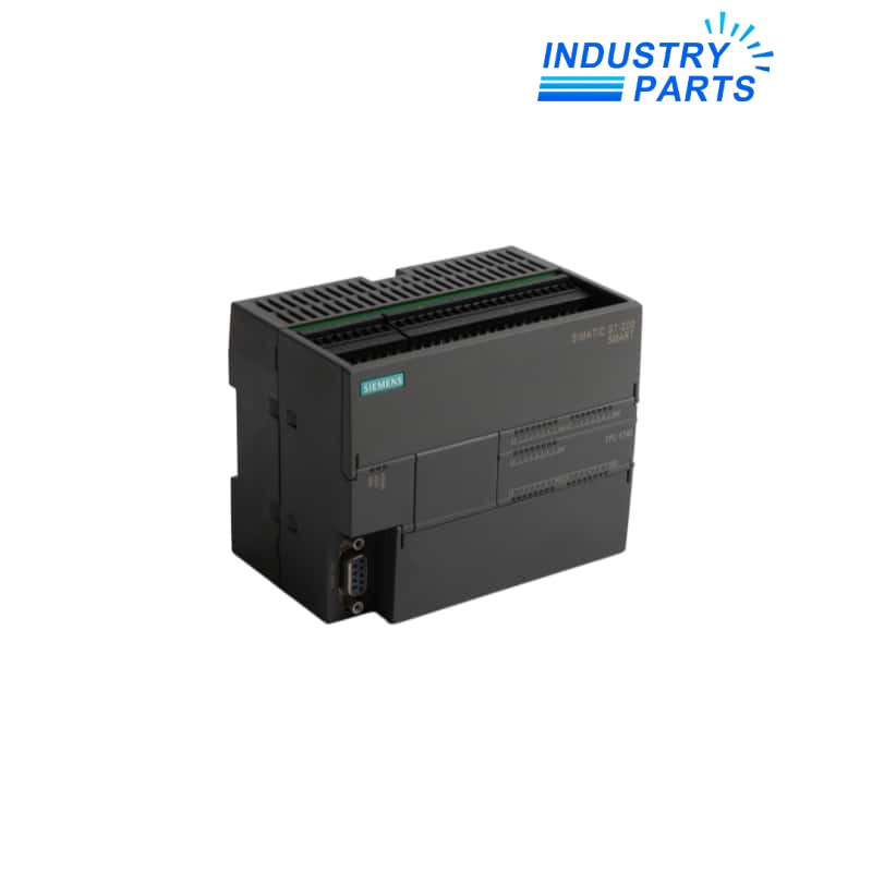
SIMATIC S7-200 SMART | DC/DC/DC CPU with onboard I/O
Siemens 6ES7288-1ST40-0AA0 SIMATIC S7-200 SMART CPU ST40
A compact ST40 controller with 24 digital inputs, 16 transistor outputs, Ethernet and RS485 communication.
BrandSiemens
Model6ES7288-1ST40-0AA0
Product TypeCompact PLC CPU
01
Key Information
6ES7288-1ST40-0AA0 is the DC/DC/DC CPU ST40 in the SIMATIC S7-200 SMART controller family. It combines processor memory, 40 onboard digital channels and the principal communication interfaces in a 125 mm-wide housing.
The article provides 24 inputs for 24 V DC signals and 16 transistor outputs for 24 V DC loads. Program development and maintenance use STEP 7 Micro/WIN SMART.
02
Functions
- Executes compact machine logic with 24 KB of program memory and 16 KB of user-data memory.
- Connects local sensors and actuators directly through the integrated 24-input and 16-output channel set.
- Provides Ethernet/PROFINET and RS485 connectivity for programming, controller communication and supported field devices.
- Accepts an optional microSDHC card for the supported transfer and maintenance workflows.
- Handles time-critical control with 150 ns bit execution and the integrated high-speed counter and pulse-output resources.
03
Specifications
| Manufacturer | Siemens |
|---|---|
| Article Number | 6ES7288-1ST40-0AA0 |
| Controller Family | SIMATIC S7-200 SMART |
| CPU Variant | ST40, DC/DC/DC |
| Rated Supply | 24 V DC |
| Permitted Supply Range | 20.4–28.8 V DC |
| Onboard Digital Inputs | 24 × 24 V DC |
| Onboard Digital Outputs | 16 × 24 V DC transistor |
| Program / Data Memory | 24 KB / 16 KB |
| Communication | 1 Ethernet/PROFINET and 1 RS485 |
| Memory-Card Option | microSDHC |
| Execution Time | 150 ns bit; 1.2 µs word; 3.6 µs floating point |
| Maximum Input Current | 680 mA |
| Maximum Power Loss | 18 W |
| Protection | IP20 |
| Engineering Software | STEP 7 Micro/WIN SMART |
| Lifecycle | Spare-part article |
04
Installation
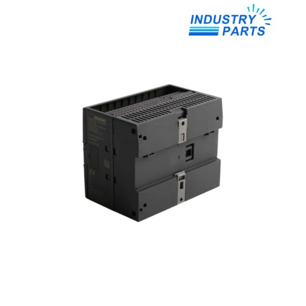
- Install the CPU on the supported DIN rail with clear access to the removable terminal blocks and communication ports.
- Use a regulated 24 V DC source within the specified operating range and separate signal wiring from high-energy conductors.
- Map the 24 input and 16 transistor-output terminals against the cabinet drawings before reconnecting field devices.
- Apply the temperature limit for the actual mounting orientation: horizontal and vertical installations have different upper limits.
- Confirm the Micro/WIN SMART project, communication addresses and any memory-card procedure before CPU replacement.
05
Lifecycle
- This AA0 article is listed for spare-part use within the S7-200 SMART family.
- Keep the complete 6ES7288-1ST40-0AA0 number because later revisions may differ in environmental or certification details.
- Archive the program, communication settings and expansion-module order before removing the installed CPU.
- A replacement review should compare onboard I/O count, output technology, firmware and network configuration as one set.


