



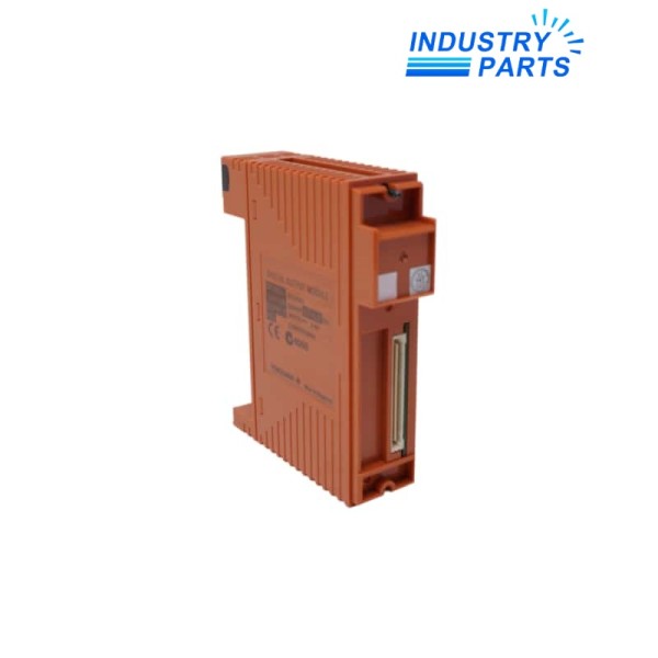
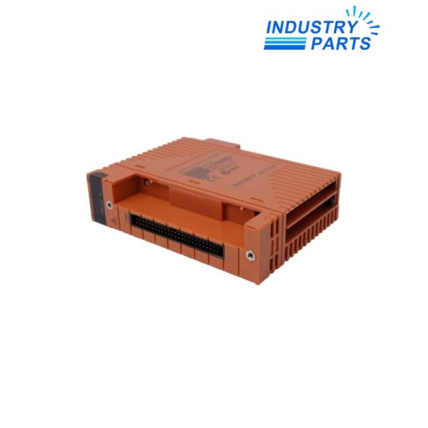
Yokogawa SDV541-S33 24 VDC Digital Output Module
A style-S3, sixteen-channel, module-isolated 24 VDC digital output module for Yokogawa safety systems.
Overview
SDV541-S33 is a Yokogawa sixteen-channel digital output module with module-level isolation and externally supplied 24 VDC source outputs. The S33 execution retains style S3 and the associated function revisions shown on the module label.
SDV541-S33 is used in ProSafe-RS architectures and can be arranged for redundant operation where the approved system design requires it. The field supply, terminal block or cable and per-channel load must be checked together.
Specs
| Manufacturer | Yokogawa |
|---|---|
| Model | SDV541-S33 |
| Product Family | ProSafe-RS safety I/O |
| Product Type | Module-isolated digital output module |
| Output Channels | 16 |
| Output Method | Current source |
| External Supply | 24 VDC nominal; 3.4 A minimum capacity |
| Supply Tolerance | +20% / -10%; selected executions may require ±5% |
| Maximum Output Current | 0.2 A per channel |
| Maximum Total Load | 3.2 A for the module, subject to safety-system restrictions |
| Minimum Load Current | 35 mA |
| Documented Load Resistance | 120 to 685 Ω |
| Maximum Output Voltage Drop | 1 V |
| Output Response Time | 30 ms or less |
| Internal Current | 300 mA maximum at 5 VDC and 150 mA maximum at 24 VDC |
| Connection Options | Pressure-clamp terminal, MIL connector or documented AKB-series cable |
| Functional Safety Context | SIL 3 applications when installed in the certified architecture |
| Style / Function Revision | S3 style; verify F1 and F2 markings on the complete label |
Features
- Provides sixteen externally powered 24 VDC source outputs in one safety I/O module.
- Supports redundant module arrangements in approved ProSafe-RS configurations.
- Offers documented terminal and cable choices for cabinet integration.
- Maintains style and function-revision markings for accessory compatibility.
Applications
- Emergency shutdown and safety interlock output circuits.
- Solenoid, relay and annunciator loads within the documented current limits.
- Redundant safety-output arrangements in ProSafe-RS systems.
Lifecycle
- Record every output assignment, load current, external supply and fuse arrangement.
- Capture the module style, F1/F2 revisions, terminal block or cable part number and redundancy pairing.
- Plan proof-test coverage and safe-state handling before exchange.
- After installation, verify de-energized safe state, commanded operation, diagnostics and application proof tests.
FAQ
Can SDV541-S33 drive any 24 VDC solenoid directly?
Only when inrush, steady current, minimum load, voltage drop, suppression and the total module load meet the documented limits.
Why must the full style and function revision be checked for SDV541-S33?
Terminal hardware, safety certification and host compatibility can depend on the S3 and F1/F2 markings, not just the base model.
Can SDV541-S33 be exchanged online in a redundant safety system?
Use only the certified ProSafe-RS maintenance procedure after confirming redundancy health, bypass controls and the safe state of every affected final element.
What should a quotation for SDV541-S33 include besides the module?
Specify the terminal block or AKB cable, external 24 VDC supply, redundancy use, load list, system release and required certification.
How should SDV541-S33 be accepted after installation?
Complete channel diagnostics and the approved proof test from logic solver command through each final element, including loss-of-power behavior.
Recommended Models
| 1769-L32E | 05704-A-0122 | 6GK1905-6AA00 |
| 2CDG120001R0011 | Wieland 57.506.0055.0 | SEGCPS4A |
| JL086A | AG1 AG6 1301110020 | MCR-SL-PT100-LP-I |
| X67AM1323 | HTT 2000 PVDF | DDS02.2-W100-B 263406 DSM02.3-FW 265398 |
| 3RA2110-0FA15-1BB4 | KFD2-UT2-1 191884 | GPS18x USB 010-00321-31 |
| JWS150-12/A | RLU232 | 6ES7954-8LF02-0AA0 |
| 8B0F0550H000.000-1 | Danfoss VLT6052HT4C54STR3DLF10A00C0 | 2CDG110167R0011 |
| SG-TL70-A | IMG 58B-500/50/1-ABC-PT-51 | 802140 |
| J9735A 2920/2930M 5080-0153 | BN 6667.2380-N2-K5-Z1-P1 | HTS-16T |
| 8BVP0220HW00.000-1 | ABB 2CDG110043R0011 | ABB TU582-S-XC 1SAP481200B0001 |


