

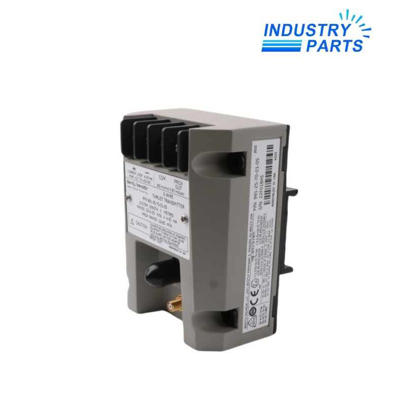


Bently Nevada 991-25-70-01-00 Thrust Transmitter
A two-wire loop-powered axial-position transmitter with DIN-rail clips and no agency-approval option.
Overview
991-25-70-01-00 is a Bently Nevada 991 Thrust Transmitter configured for a 25-0-25 mil measurement range and a 7 m 3300 NSv transducer system. Its mounting option supplies 35 mm DIN-rail clips.
The transmitter integrates Proximitor Sensor electronics and converts axial position into a 4–20 mA loop signal for machinery monitoring or control systems.
Specs
| Manufacturer | Bently Nevada, a Baker Hughes business |
|---|---|
| Complete Model | 991-25-70-01-00 |
| Product Family | 991 Thrust Transmitter |
| Measurement Range | 25-0-25 mils |
| Transducer System Length | 7.0 m |
| Mounting Hardware | 35 mm DIN-rail clips |
| Agency Approval Option | Not required |
| Output | 4–20 mA proportional to axial position |
| Loop Power | 12 to 35 V DC |
| Matched Sensor Input | One 3300 NSv probe and extension cable |
Features
- Two-wire operation carries power and measurement on the same current loop.
- Front-access zero and span controls support field calibration of the selected range.
- PROX OUT and COM connections provide direct diagnostic access to the transducer signal.
- A power-up inhibit and fast Not OK response help prevent misleading current output during fault conditions.
Applications
- Axial-position monitoring on small centrifugal compressors and pumps.
- Thrust observation on motors, fans and original-equipment machinery.
- Retrofit loops that require a standard 4–20 mA signal from a matched NSv proximity system.
Lifecycle
- Record the installed probe, extension cable, target material and physical gap before removal.
- Confirm that probe plus extension-cable length totals 7 m.
- Preserve loop scaling, alarm thresholds and polarity in the receiving control system.
- Perform zero, span, Not OK and diagnostic-signal checks after replacement.
FAQ
What is the most important compatibility check for 991-25-70-01-00?
The 3300 NSv probe and extension cable must form the specified 7 m system and be suitable for the target and installed geometry.
Does 991-25-70-01-00 include hazardous-area approvals?
No. The final 00 selects no agency approval; use the exact approved execution when the site classification requires it.
Can 991-25-70-01-00 replace a metric-range 991 transmitter?
No direct substitution should be made because span, calibration and receiving-system scaling would differ.
What loop data should accompany a request for 991-25-70-01-00?
Provide supply voltage, loop resistance, controller input scaling, alarm setpoints and any barriers or isolators.
Which tests should be documented after installing 991-25-70-01-00?
Document mechanical gap, zero and span response, 4–20 mA scaling, fault current behavior and the diagnostic signal.
Is a nearby 991 suffix equivalent to 991-25-70-01-00?
No. Range, total system length, mounting kit and approval code are all functional ordering fields.
Recommended Models
| FP2SS 8024 B14A | PNOZ s7.1 750167 | RZ01 56030100 |
| 6ES7416-2FK02-0AB0 | QUINT-PS-100-240AC | JUSP-NS115 |
| CS510 | FA87 CM3C100L-45A-P/BZ/PK/AK0H/SBB | Reis Lasertec 200000 Rev:2.1 |
| LT-800-072 | 6ES7972-0BB42-0XA0 | PSM-EG-RS485W2/FO-E/G |
| CR104PBG91B3 | MPSR2-SHTW-GE | KA47 CM71L/TF/RH1M/SM60 |
| 6321001A | MPR200 496600 299552 | OM31BHONDT 900PTNTEK0045M-H001 |
| 10007591.3 | JZ10-11-PT15 | Saflok 74350 |
| M-ME-D204-12 | GV4P80B | ETC 4260A1014 |
| 6ES5430-6AA11 | X67SM2436 | 3RK1304-0HS00-6AA0 |
| ATS48D47Q | ECT-16-0045 | T9S Version: 2.2 |


