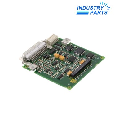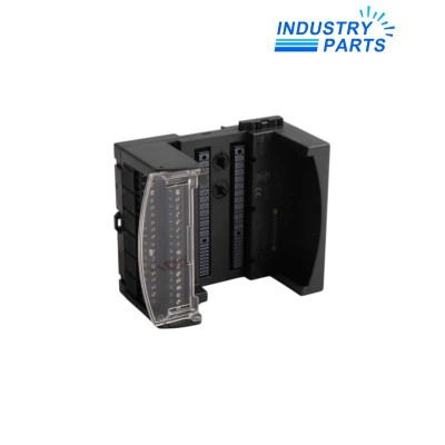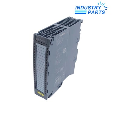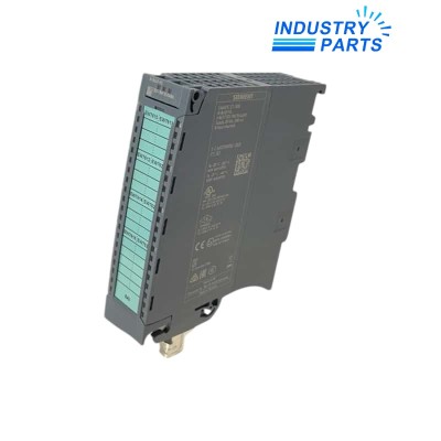
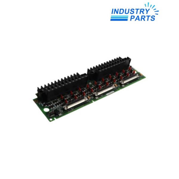
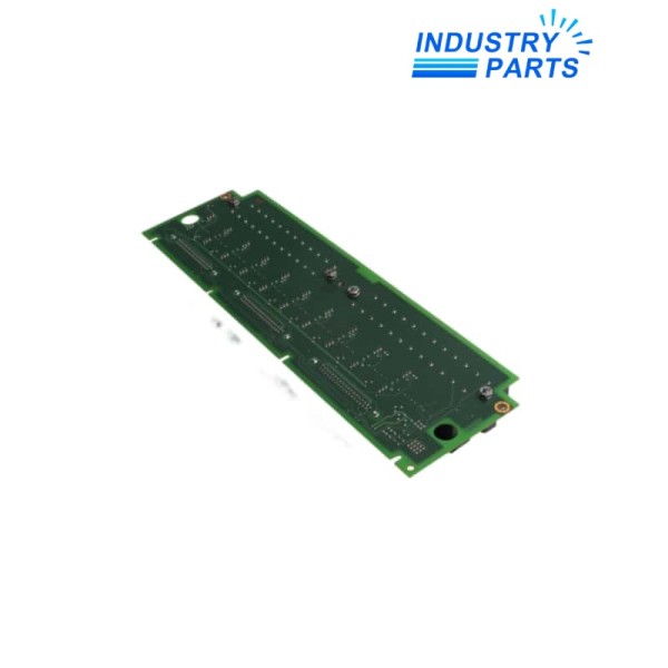
GE IS200TBAIH1CDC Analog I/O Terminal Board
A TBAI field termination board for ten analog inputs and two analog outputs in simplex or triple-redundant turbine-control architectures.
Key Information
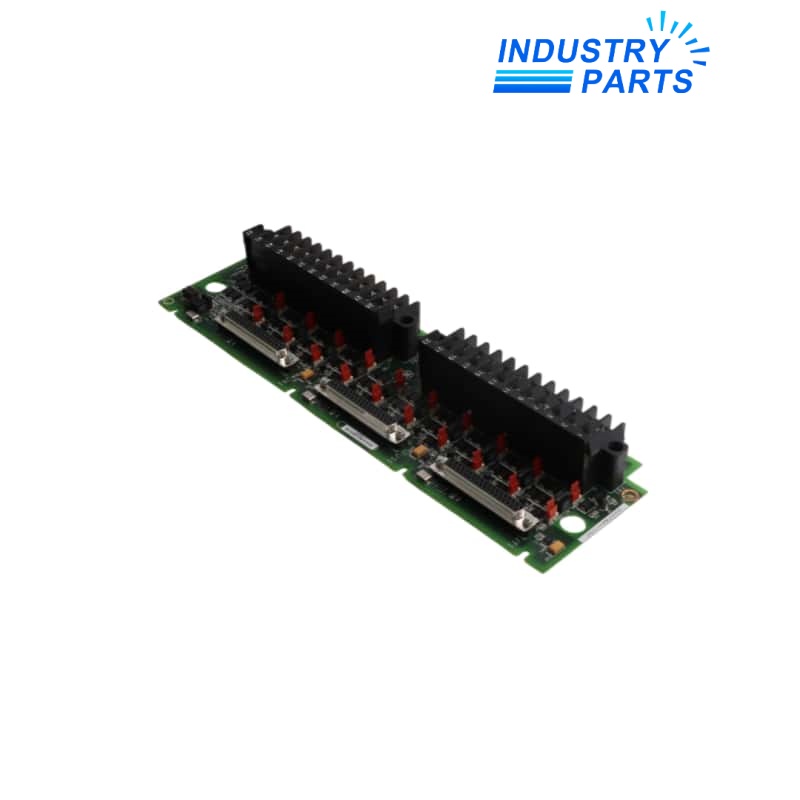
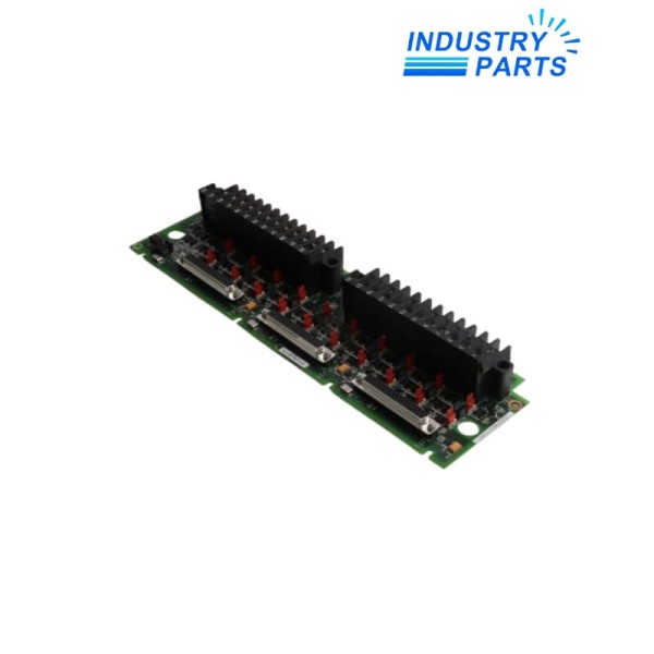
IS200TBAIH1CDC is a GE TBAI analog input/output terminal board identified by the complete H1CDC hardware and revision string. The TBAI design provides ten analog input circuits and two analog output circuits for Mark VI-family turbine-control systems.
The terminal board accepts two-wire, three-wire, four-wire and externally powered transmitters. Three 37-pin D-sub connectors fan signals to the associated I/O processors for simplex or TMR arrangements, while onboard suppression protects field circuits from surge and high-frequency noise.
Functions
- Terminates ten field analog input circuits and two analog output circuits.
- Supports current and voltage transmitter arrangements through documented jumper selections.
- Fans input signals to R, S and T processor paths in TMR applications.
- Combines the three output-driver currents in TMR operation for regulated analog output control.
- Provides barrier-style field wiring, shield termination and signal protection at the cabinet interface.
Specifications
| Manufacturer | GE |
|---|---|
| Model | IS200TBAIH1CDC |
| Functional Acronym | TBAI |
| Product Type | Analog input/output terminal board |
| System Family | Mark VI / Mark VIe turbine control |
| Analog Inputs | 10 |
| Analog Outputs | 2 |
| Supported Transmitters | Two-wire, three-wire, four-wire and externally powered |
| Input Selection | Current or voltage by documented jumper configuration |
| Output Configuration | 0–20 mA; one output circuit can support the documented 0–200 mA selection |
| Processor Connectors | Three 37-pin D-sub connectors: JR1, JS1 and JT1 |
| Redundancy | Simplex through JR1 or TMR through all three processor paths |
| Signal Protection | Surge and high-frequency noise suppression |
| Field Connection | Barrier-type terminal blocks with adjacent shield bar |
| Revision Identity | H1CDC must remain complete in the quotation and receiving record |
| Compatibility Control | Confirm the installed VAIC/PAIC path, cable set, jumpers and system guide revision |
Installation
- Photograph the IS200TBAIH1CDC label, jumpers, terminal blocks, shield bar and all JR1/JS1/JT1 cables before disconnection.
- Export the channel configuration and record transmitter type, range, loop power and polarity for all twelve circuits.
- Isolate field energy and use the turbine-control maintenance procedure for the active redundancy architecture.
- Transfer jumpers and wiring only from a checked channel schedule, not from board appearance.
- Calibrate every input and output, then verify diagnostics, voting and controller indications before return to service.
Lifecycle
- Keep the H1CDC revision with the board history, cable schedule and channel map.
- Inspect removable terminals, shields, connector latches and surge-damaged components during outages.
- Trend channel drift and voting mismatch so field-loop problems are not misclassified as terminal-board faults.
- Treat a different TBAI group or revision as a compatibility review involving I/O processor, cables, jumpers and software.
FAQ
What evidence makes an IS200TBAIH1CDC quotation revision-safe?
Provide clear front and rear labels, H1CDC revision, Mark VI/VIe cabinet identity, associated I/O processor, JR1/JS1/JT1 cable numbers, jumper map and terminal photographs.
Can IS200TBAIH1CDC be commissioned by copying wire positions alone?
No. Each channel also depends on transmitter type, loop power, polarity, range and jumper selection; these must be verified against the engineering drawings.
How should IS200TBAIH1CDC be tested in a TMR system?
Inject known signals, compare all three processor paths, verify voting diagnostics and prove each analog output under the approved turbine-control test plan.
What should be checked if an IS200TBAIH1CDC input drifts after replacement?
Check jumper position, shield grounding, loop supply, cable continuity, target transmitter calibration, connector seating and agreement among redundant processor readings.
Can another TBAI revision replace IS200TBAIH1CDC without review?
Only after GE documentation, board compatibility, processor/cable interfaces, jumper functions and the site configuration have been checked for the exact alternate.