

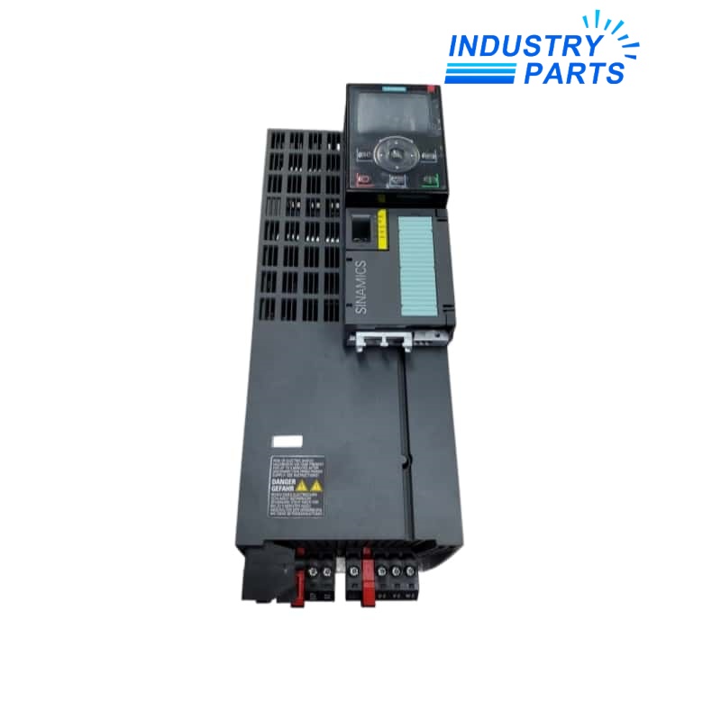
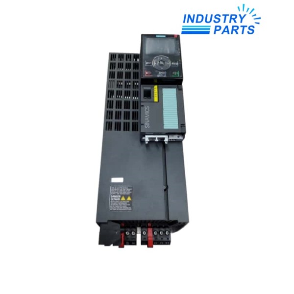
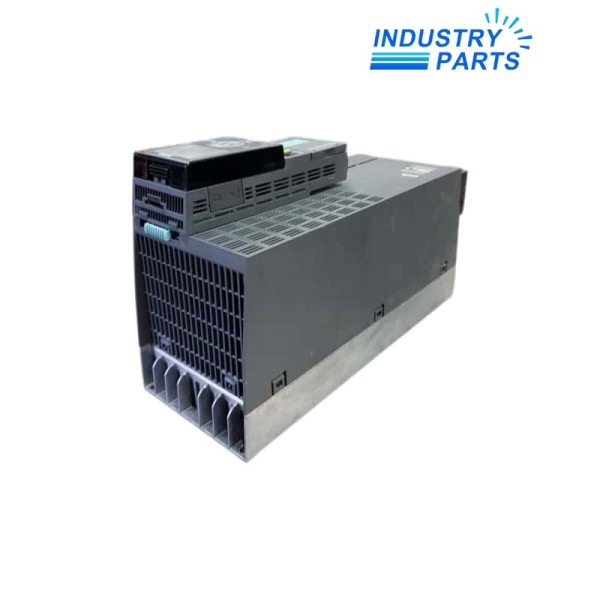
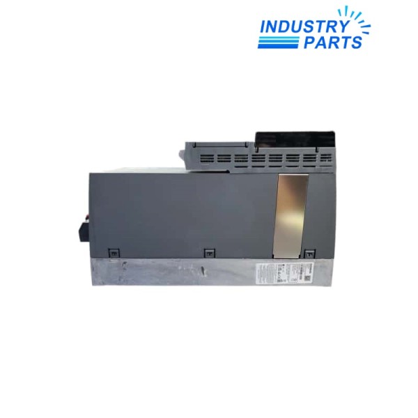
SINAMICS G120 | FSC power stage without input filter
Siemens 6SL3210-1PE23-3UL0 SINAMICS PM240-2 Power Module
An unfiltered 15 kW low-overload PM240-2 power module with integrated braking chopper for modular G120 systems.
BrandSiemens
Model6SL3210-1PE23-3UL0
Product TypeUnfiltered Modular Drive Power Module
01
Key Information
6SL3210-1PE23-3UL0 is the unfiltered FSC version of the SINAMICS PM240-2 modular power stage. It is rated for 15 kW low-overload duty or 11 kW high-overload duty on a three-phase 380 to 480 V supply.
The module includes a braking chopper but no integrated input filter. EMC compliance therefore depends on the engineered external measures, cable arrangement and installation environment.
02
Functions
- Delivers variable-frequency motor power under the control of a compatible SINAMICS G120 control unit.
- Supports the documented low- and high-overload profiles for general and higher-torque applications.
- Routes braking energy to an external resistor through the built-in chopper when the application requires dynamic braking.
- Allows longer motor-cable configurations within the separate limits stated for shielded and unshielded cables.
- Provides an unfiltered power stage for installations where EMC filtering is engineered elsewhere in the system.
03
Specifications
| Manufacturer | Siemens |
|---|---|
| Article Number | 6SL3210-1PE23-3UL0 |
| Product Family | SINAMICS G120 PM240-2 |
| Input Supply | 3 AC 380–480 V, +10 / -10%, 47–63 Hz |
| Low-Overload Rating | 15 kW at -10 to +40 °C |
| High-Overload Rating | 11 kW at -10 to +50 °C |
| Overload Profile | 200% for 3 s / 150% for 57 s / 100% for 240 s |
| Input Filter | Not integrated |
| Braking Chopper | Integrated |
| Frame Size | FSC |
| Protection | IP20 without control unit or operator panel |
| Motor Cable Length | Up to 50 m shielded or 100 m unshielded |
| Power Connections | Plug-in screw terminals, 6–16 mm² |
| Cooling Airflow | 0.018 m³/s |
| Installation Altitude | Up to 1,000 m without derating |
| Efficiency Class | IE2 |
04
Installation
- Define the EMC concept before installation because the UL0 article does not contain an input filter.
- Keep shielded and unshielded motor cables within their respective length limits and terminate shields with low impedance.
- Provide the specified FSC ventilation clearances and verify cabinet heat removal for the selected duty class.
- Select the external braking resistor from the motor inertia, stopping time and permissible chopper duty.
- Confirm the control-unit firmware, line protection and 6–16 mm² power-terminal conductor range before wiring.
05
Lifecycle
- The complete UL0 suffix is essential because it identifies the unfiltered configuration.
- A like-for-like review should compare frame size, overload duty, input-filter arrangement, control-unit firmware and braking hardware.
- Retain the parameter backup and motor data with the service record even though they reside in the control-unit configuration.
- Use the current Siemens article documentation available for this exact order number when planning future service.


