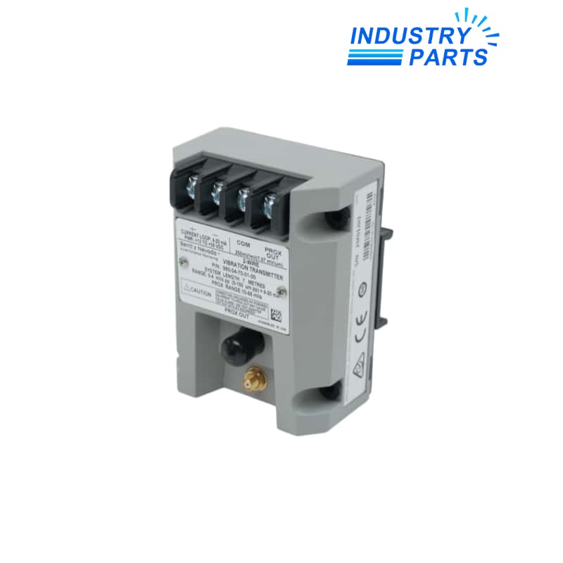
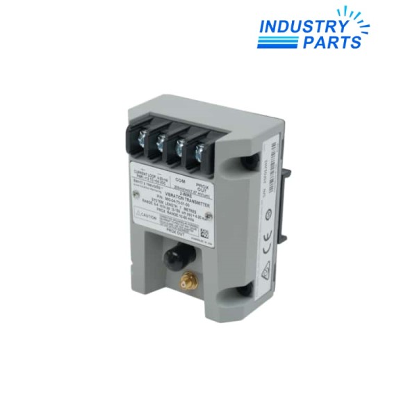
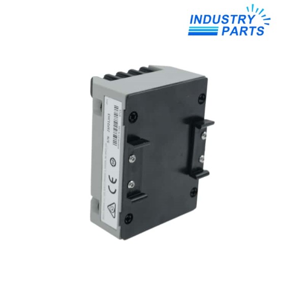
Bently Nevada 990-04-70-01-01 Vibration Transmitter
A loop-powered transmitter configured for a 3300 NSv proximity chain and direct machinery-control integration.
Key Information
990-04-70-01-01 is a Bently Nevada two-wire vibration transmitter for one matching 3300 NSv probe and extension cable. It converts the proximity signal into an industry-standard current loop for compact rotating-equipment monitoring.
The complete ordering code identifies its measuring span, total system length, DIN-rail mounting and hazardous-location approval. Those suffixes should remain intact during quotation and replacement review.
Functions
- Conditions one non-contacting eddy-current proximity channel for radial vibration measurement.
- Feeds a proportional loop signal into a machinery control or monitoring input without a separate monitor rack.
- Provides a buffered proximity output for setup, troubleshooting and waveform observation.
- Drives the loop below the normal measurement band when the probe system is not OK.
Specifications
| Manufacturer | Bently Nevada, a Baker Hughes business |
|---|---|
| Complete Model | 990-04-70-01-01 |
| Full-Scale Range | 0 to 4 mil peak-to-peak (0 to 100 µm peak-to-peak) |
| System Length | 7.0 m (23.0 ft) |
| Mounting Option | 35 mm DIN-rail clips |
| Agency Approval | CSA Division 2 |
| Compatible Sensor Chain | 3300 NSv probe and extension cable |
| Power Input | +12 to +35 VDC at transmitter terminals |
| Loop Output | 4 to 20 mA DC, two-wire |
| Frequency Response | 5 Hz to 6 kHz (+0 / −3 dB) |
| Probe Gap Window | 0.5 to 1.75 mm (20 to 55 mil) |
| Maximum Loop Resistance | 1000 Ω at 35 VDC |
Installation
- Confirm that the probe and extension cable form the ordered total-length system before mounting the transmitter.
- Install the DIN clips securely, maintain cable separation from power conductors and terminate the loop with the documented polarity.
- Set the probe gap within the usable linear region before adjusting zero and span.
- Commission the complete loop under the applicable CSA installation drawing and prove the control-system alarm response.
Lifecycle
- Keep the transmitter, probe and extension-cable identities together as one calibrated measurement chain.
- Record final gap voltage, loop scaling and alarm setpoints after every sensor-chain intervention.
- Inspect connector condition, cable routing and shield termination during planned machinery outages.
FAQ
Can 990-04-70-01-01 be replaced by another 990 transmitter with a similar label?
Only when the full-scale option, system length, mounting and approval suffixes all match the installed measurement loop.
Which field components must be checked before ordering 990-04-70-01-01?
Verify the 3300 NSv probe, extension-cable length, target material, loop supply, receiving input and hazardous-area drawing.
Why can 990-04-70-01-01 indicate a low current instead of a vibration value?
An out-of-range probe gap, open or shorted sensor wiring, or a power-up inhibit can place the transmitter in its not-OK state.
Does 990-04-70-01-01 need a separate vibration monitor rack?
No rack is required for basic conversion, but the receiving control system must provide correct loop power, scaling, alarms and protection logic.
What should be tested after installing 990-04-70-01-01?
Check sensor gap, buffered output, loop endpoints, polarity, alarm behavior and the final machinery-control indication.
What information helps IndustryParts quote 990-04-70-01-01 accurately?
Send the complete transmitter code, probe and cable labels, cabinet photographs, area classification and receiving-channel details.